-
E-mail
980227448@qq.com
-
Phone
15307180902
-
Address
Room 2003, 20th Floor, Building A, Luojiashan Building, No.7 Luojiashan Road, Hongshan District, Wuhan City
Product Categories
Wuhan Baishi Automation Equipment Co., Ltd
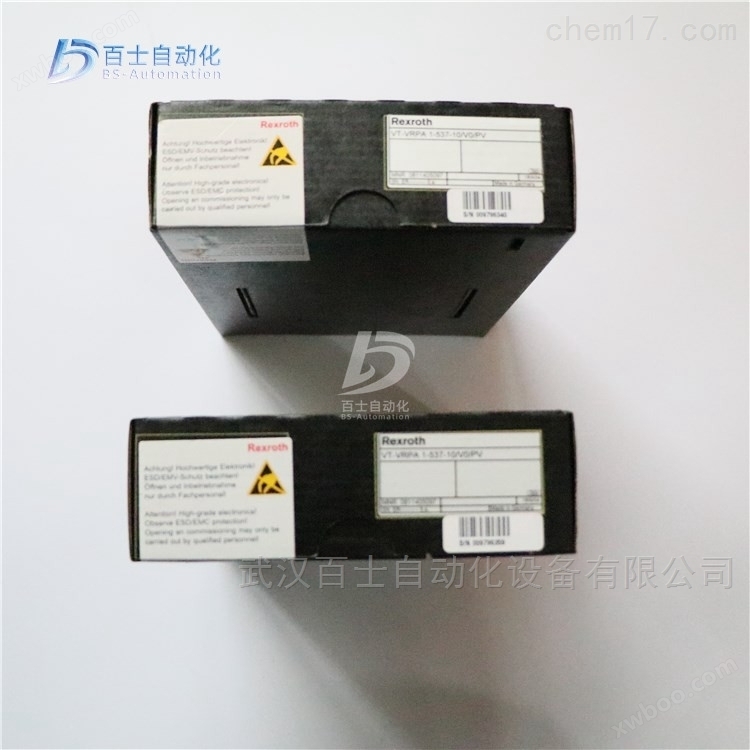
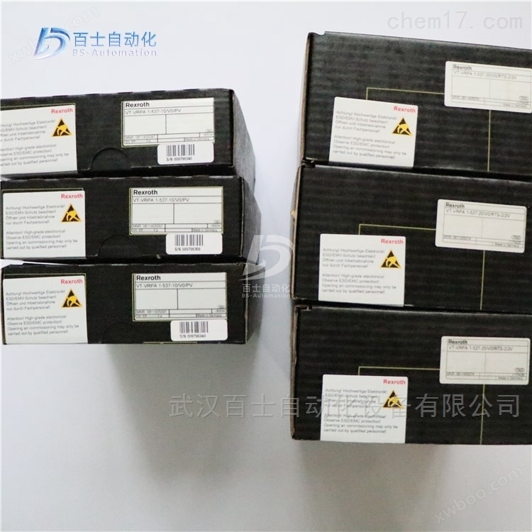
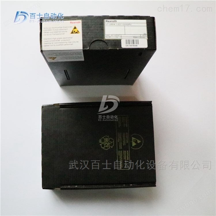
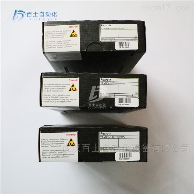
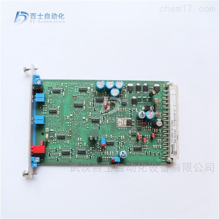
Rexroth proportional valve enlarged version 0811405104
NegotiableUpdate on 01/22
- Model
- Nature of the Manufacturer
- Producers
- Product Category
- Place of Origin
Overview
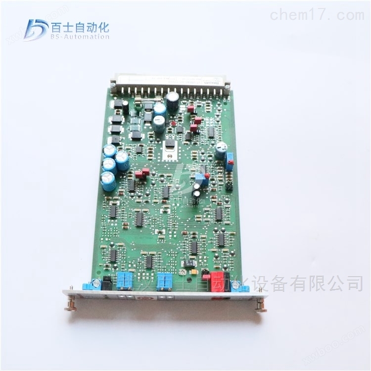
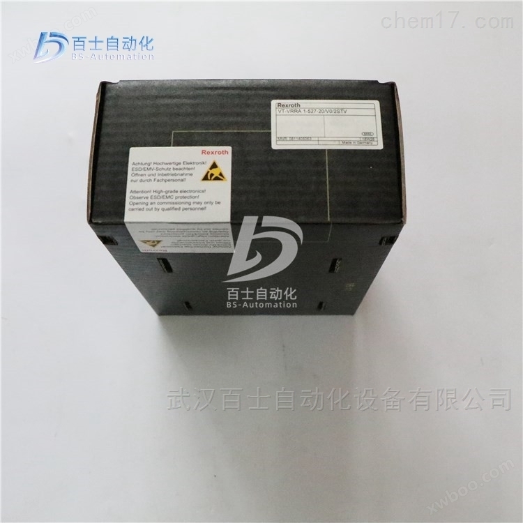
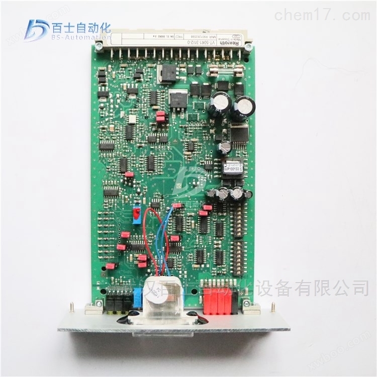
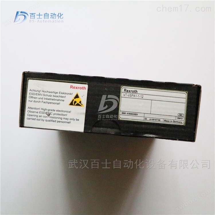
Rexroth Proportional Valve Amplification Version 0811405104 VT-VRPA1-537-10/V0/QV-RTP, German REXROTH Amplification Version, Rexroth Proportional Valve Amplification Version, REXROTH Analog Circuit Amplification Version, Rexroth Amplifier
Product Details
Rexroth proportional valve enlarged version 0811405104VT-VRPA1-537-10/V0/QV-RTP, German REXROTH amplification version, ReXROTH proportional valve amplification version, REXROTH analog circuit amplification version, ReXROTH amplifier, Wuhan Baishi Automation Equipment Co., Ltd. specializes in selling products that are original from the factory and refuse high imitation counterfeit goods. Customers can buy and use with peace of mind. *Common products available in stock, welcome new and old customers to inquire and purchase!


The amplifier adopts a simple amplification principle, either amplifying the signal at the transmitting end or amplifying the attenuated signal at the receiving end. The amplification method at the receiving end is immediately abandoned because it amplifies interference during transmission, including crosstalk between internal signals. By using a specially designed VGA video cable as the transmission medium, devices that amplify the sending end can transmit VGA video signals from the computer for tens of meters.
Proportional electromagnets must have sufficient current to overcome spring force and hydraulic force output. Different manufacturers of proportional electromagnets typically require a current value ranging from 600-3000mA for large displacement, while industrial control standard signals are usually 0-5v/0-10v/-5-+5V/-10-+10v voltage signals or 0-20mA/4-20mA current signals. The control signal has weak load capacity and is not sufficient to drive the proportional electromagnet. The proportional valve amplifier plays a role in signal matching, receiving weak control signals and outputting the current required by the proportional electromagnet. At the same time, the proportional valve amplifier adds various necessary links, such as dead zone adjustment/gain adjustment/ramp time/flutter adjustment, etc. In short, a proportional valve amplifier is a signal matching device.
A device that increases signal amplitude or power, which is an important component for processing signals in automation technology tools. The amplification function of an amplifier is achieved by controlling the energy source with the input signal, and the power consumption required for amplification is provided by the energy source. For linear amplifiers, the output is the reproduction and enhancement of the input signal. For nonlinear amplifiers, the output is a certain function of the input signal. Amplifiers are divided into mechanical amplifiers, electromechanical amplifiers, electronic amplifiers, hydraulic amplifiers, and pneumatic amplifiers according to the physical quantities of the signals they process, among which electronic amplifiers are widely used.
With the promotion of jet technology (see jet components), the application of hydraulic or pneumatic amplifiers is gradually increasing. Electronic amplifiers are divided into vacuum tube amplifiers, transistor amplifiers, solid-state amplifiers, and magnetic amplifiers according to the active devices used, among which transistor amplifiers are widely used. In automation instruments, transistor amplifiers are commonly used for signal voltage amplification and current amplification, mainly in the form of single ended amplification and push-pull amplification. In addition, it is commonly used for impedance matching, isolation, current voltage conversion, charge voltage conversion (such as charge amplifiers), and using amplifiers to achieve a certain functional relationship between output and input (such as operational amplifiers).
Electro hydraulic proportional valve is a component that generates corresponding actions based on the input voltage signal of the proportional solenoid inside the valve, causing displacement of the valve core and changes in the size of the valve port, thereby completing pressure and flow output components proportional to the input voltage. The displacement of the valve core can also be fed back in mechanical, hydraulic, or electrical forms. The electro-hydraulic proportional valve has various advantages, such as diverse forms, easy composition and use of electrical and computer control of various electro-hydraulic systems, high control accuracy, flexible installation and use, and strong anti pollution ability. Its application fields are increasingly expanding. In recent years, the development and production of plug-in proportional valves and proportional multi way valves have fully considered the characteristics of engineering machinery use, and have functions such as pilot control, load sensing, and pressure compensation. Its appearance is of great significance for improving the overall technical level of mobile hydraulic machinery. Especially in terms of electronic control pilot operation, wireless remote control, and wired remote control operation, it has demonstrated its good application prospects.
Types and forms of electro-hydraulic proportional valves
Electro hydraulic proportional valves include proportional flow valves, proportional pressure valves, and proportional directional valves. The hydraulic operation characteristics of construction machinery can be divided into two main types of electro-hydraulic proportional valves based on their structural forms: one is the screw insertion proportional valve, and the other is the slide valve proportional valve.
The slide valve proportional valve, also known as the distribution valve, is one of the basic components of mobile mechanical hydraulic systems and is a composite valve that can achieve directional and flow regulation. The electro-hydraulic slide valve proportional multi way valve is an ideal electro-hydraulic conversion control component. It retains the basic functions of a manual multi way valve and also adds control methods such as position electric feedback proportional servo operation and load sensing. It is a replacement product for engineering machinery distribution valves.
Due to manufacturing cost considerations and low precision requirements for engineering machinery control, the proportional multi way valve generally does not have displacement sensing sensors and has electronic detection and error correction functions. The displacement of the valve core is easily affected by pressure fluctuations caused by load changes, and visual observation is necessary to ensure the completion of the operation. Attention should be paid to external influences when operating electronic control and remote control. Recently, with the development of electronic technology, more and more people are using displacement sensors such as internal differential transformers (LDVT) to detect the movement of valve cores, achieving closed-loop control of valve core displacement. This highly integrated proportional valve, consisting of an electromagnetic proportional valve, position feedback sensor, driver amplifier, and other electronic circuits, has a certain correction function and can effectively overcome one The disadvantage of proportional valves is that they greatly improve control accuracy.
Rexroth proportional valve enlarged version 0811405104VT-VRPA1-537-10/V0/QV-RTP, German REXROTH amplification version, Rexroth proportional valve amplification version, REXROTH analog circuit amplification version, Rexroth amplifier
Rexroth REXROTH valve amplifier with electric position feedback proportional valve
Rexroth REXROTH Analog Amplification Module
R900752430 VT-MRMA1-1-1X/V0/0
R900779644 VT-MRPA1-100-1X/V0/0
R901080965 VT-MRPA1-150-1X/V0/0
R901080966 VT-MRPA1-151-1X/V0/0
R901416700 VT-MRPA1-151-1X=V0/0
R901094750 VT-MRPA1-1-1X/V0/0
R901094751 VT-MRPA1-2-1X/V0/0
R900249895 VT-MRPA2-1-1X/V0/0
R900249811 VT-MRPA2-2-1X/V0/0
Rexroth REXROTH analog circuit amplification version, European version standard
0811405095 VT-VRPA1-527-10/V0
0811405096 VT-VRPA1-527-10/V0/PV
0811405098 VT-VRPA1-527-10/V0/QV
0811405097 VT-VRPA1-537-10/V0/PV
0811405099 VT-VRPA1-537-10/V0/QV
0811405101 VT-VRPA1-527-10/V0/PV-RTP
0811405103 VT-VRPA1-527-10/V0/QV-RTP
0811405100 VT-VRPA1-527-10/V0/RTP
0811405102 VT-VRPA1-537-10/V0/PV-RTP
0811405104 VT-VRPA1-537-10/V0/QV-RTP
081145074 vt -vrppa1-527-20 / V0 / RTs -2 / 2V
R978022097 VT-VRPA1-100-1X/SO43A-466B
R901009038 VT-VRPA1-100-1X/V0/0
R901057058 VT-VRPA1-150-1X/V0/0
R901057060 VT-VRPA1-151-1X/V0/0
R901057060 VT-VRPA1-151-11/V0/0
R901057060 VT-VRPA1-151-12/V0/0
R900952202 VT-VRPA1-50-1X/
R900619297 VT-VRPA1-50-1X/001 FEDERLEIST 32POLIG F
R978911504 VT-VRPA1-50-1X/SO43A-472B
R900952204 VT-VRPA1-51-1X/
R979810986 VT-VRPA1-51-1X/ SO41-7519
R978031853 VT-VRPA1-51-1X/SO43A-1828
R900952205 VT-VRPA1-52-1X/
R900979887 VT-VRPA2-1-1X/V0/T1
R900979887 VT-VRPA2-1-11/V0/T1
R900979885 VT-VRPA2-1-1X/V0/T5
R900979889 VT-VRPA2-2-1X/V0/T1
R900979888 VT-VRPA2-2-1X/V0/T5
R900067617 VT-VRM1-1-1X/
Die casting machine is a machine used for pressure casting. Including two types: hot press chamber and cold press chamber. Later, they were further divided into two types: straight and horizontal. The die-casting machine, under pressure, injects molten metal into the mold for cooling and forming. After opening the mold, solid metal castings can be obtained, which were initially used for die-casting lead type.
The die-casting machine is mainly composed of various parts such as the mold closing mechanism, injection mechanism, hydraulic system, and electric control system. In addition, the die-casting machine also has components and machine bases, other devices, auxiliary devices, and other parts.
Mold closing mechanism
Drive the die-casting mold to close and open. After the mold is closed, it has sufficient ability to lock the mold tightly, ensuring that the parting surface of the mold will not expand during the injection filling process. The force that locks the mold is called the locking force (also known as the fitting force), measured in kilonewtons (kN), and is the primary parameter that characterizes the size of the die-casting machine.
Injection mechanism
Push the molten metal in the pressure chamber at the prescribed speed, with sufficient energy to flow through the sprue and sprue in the mold, and then fill the mold cavity. Then, maintain a certain pressure to transfer to the solidifying molten metal until a die casting is formed. After all the injection actions are completed, the injection punch returns to its original position.
hydraulic system
Provide sufficient power and energy for the operation of the die-casting machine.
electric control system
Control the execution actions of each mechanism of the die-casting machine to run according to the predetermined program.
The general term for various types of machinery and devices used in the plastic processing industry. Some universal machinery and equipment for transporting, separating, crushing, grinding, and drying fluids and solids also play an important role in the plastic processing industry, so they are often listed as plastic machinery. The design and manufacturing of modern plastic machinery rely not only on the development of mechanical engineering and materials science, but also closely related to the progress of theoretical research in plastic engineering.
According to the production process of plastic products, plastic machinery can be divided into four categories: plastic mixing machinery, plastic molding machinery, plastic secondary processing machinery, and plastic processing auxiliary machinery or devices. Plastic mixing machinery is used for the manufacturing of various forms of plastic mixing materials, including kneading machines, plasticizing machines (open and internal mixers), granulators, screening machines, crushers, and grinders. Plastic molding machinery, also known as plastic primary processing machinery, is used for the molding of plastic semi-finished or finished products, including compression molding machines, injection molding machines, extruders, blow molding machines, calendering machines, rolling molding machines, foaming machines, etc. Plastic secondary processing machinery is used for the reprocessing and post-treatment of plastic semi-finished or finished products, including thermoforming machines, welding machines, heat sealing machines, hot stamping machines, vacuum evaporation machines, flocking machines, printing machines, etc. Metal processing machines are also commonly used for secondary processing of plastics. Plastic processing auxiliary machinery or devices are used to rationalize the plastic processing process, including automatic measuring and feeding devices, automatic scrap recycling devices, automatic removal devices for injection molded products, rapid replacement devices for injection molds, injection mold cooling machines, automatic thickness measuring devices, and raw material conveying and storage equipment. These types of auxiliary machinery or devices have become a part of modern plastic processing automation.
The level of perfection of plastic machinery directly affects the quality, output, and cost of plastic semi-finished or finished products. Therefore, it must be able to adapt to the temperature and stress changes during the plastic mixing and processing process, as well as the resulting changes in the properties of molten materials, and adapt to special conditions such as chemical corrosion and mechanical wear. The upgrading of plastic grades, the development of engineering plastics, the emergence of composite materials, and the development of technologies such as large-scale, lightweight, and thin-walled plastic product structures require plastic machinery to achieve complete sets for product production purposes; High speed, labor-saving, and automation to improve product production efficiency; Ensure precision with minimal errors in product specifications and quality; Low energy consumption, minimal land occupation, easy and safe operation and maintenance.

Composition and function of hydraulic system
A complete hydraulic system consists of five parts, namely power components, actuating components, control components, auxiliary components (accessories), and hydraulic oil.
The function of power components is to convert the mechanical energy of the prime mover into hydraulic pressure energy, referring to the oil pump in the hydraulic system, which provides power to the entire hydraulic system. The structural forms of hydraulic pumps generally include gear pumps, vane pumps, and plunger pumps.
The function of executing components such as hydraulic cylinders and hydraulic motors is to convert the pressure energy of liquids into mechanical energy, driving loads to perform linear reciprocating or rotary motion.
Control components (i.e. various hydraulic valves) control and regulate the pressure, flow rate, and direction of fluids in hydraulic systems. According to the different control functions, hydraulic valves can be divided into village force control valves, flow control valves, and directional control valves. Pressure control valves are divided into relief valves (safety valves), pressure reducing valves, sequence valves, pressure relays, etc; Flow control valves include throttle valves, regulating valves, diversion and collection valves, etc; Directional control valves include one-way valves, hydraulic control one-way valves, shuttle valves, directional valves, etc. According to different control methods, hydraulic valves can be divided into switch type control valves, fixed value control valves, and proportional control valves.
Auxiliary components include oil tank, oil filter, oil pipe and pipe joint, sealing ring, quick change joint, high-pressure ball valve, rubber hose assembly, pressure measuring joint, pressure gauge, oil level and temperature gauge, etc.
Hydraulic oil is the working medium for transmitting energy in hydraulic systems, which includes various types such as mineral oil, emulsion, and synthetic hydraulic oil.
Hydraulic system structure
The hydraulic system consists of two parts: signal control and hydraulic power. The signal control part is used to drive the control valve action in the hydraulic power part.
The hydraulic power part is represented by a circuit diagram to indicate the interrelationships between different functional components. The hydraulic source contains a hydraulic pump, an electric motor, and hydraulic auxiliary components; The hydraulic control part contains various control valves, which are used to control the flow rate, pressure, and direction of the working oil; The execution part contains hydraulic cylinders or hydraulic motors, which can be selected according to actual requirements.
Similar Product Recommend