-
E-mail
980227448@qq.com
-
Phone
15307180902
-
Address
Room 2003, 20th Floor, Building A, Luojiashan Building, No.7 Luojiashan Road, Hongshan District, Wuhan City
Product Categories
Wuhan Baishi Automation Equipment Co., Ltd
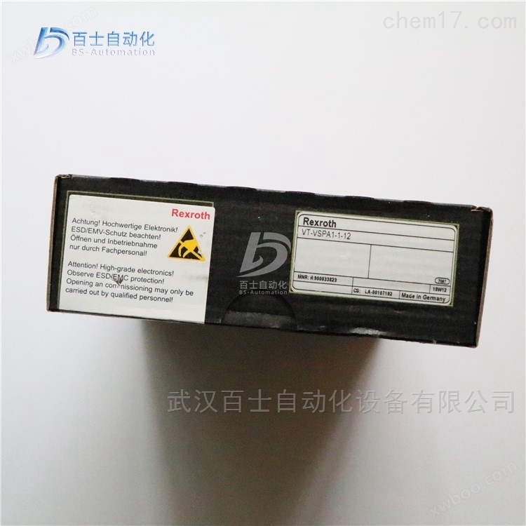
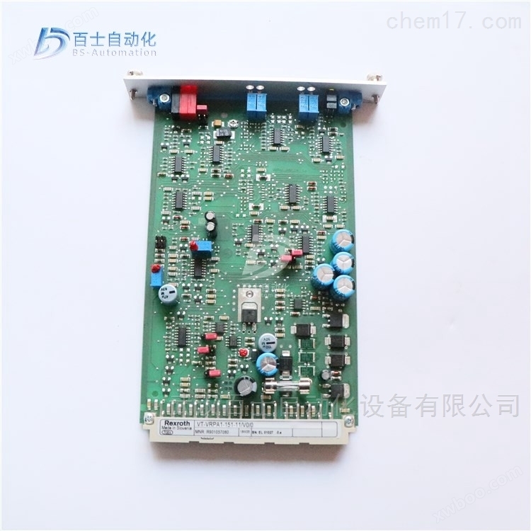
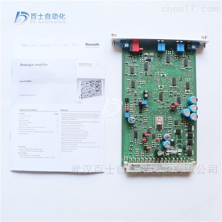
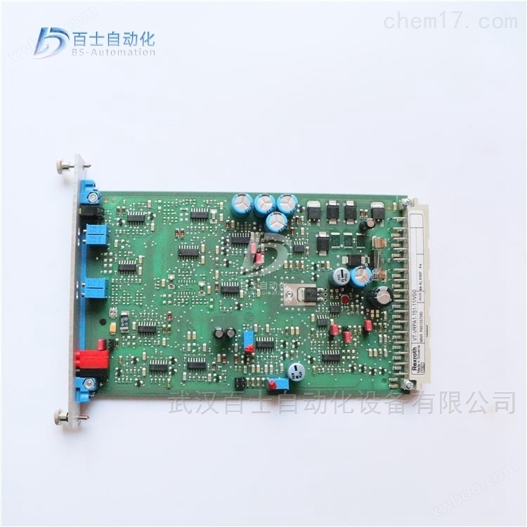
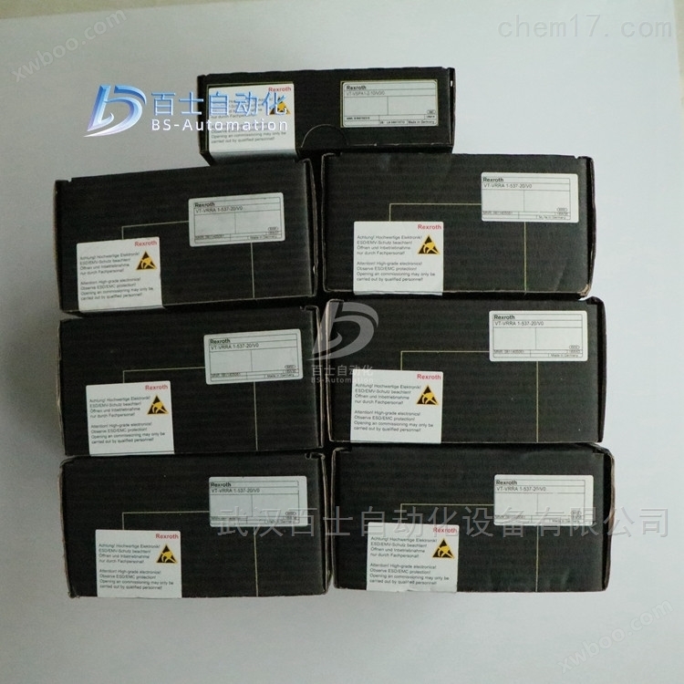
REXROTH proportional valve enlarged version 0811405126
NegotiableUpdate on 01/22
- Model
- Nature of the Manufacturer
- Producers
- Product Category
- Place of Origin
Overview
REXROTH proportional valve amplification version 0811405126 VT-MSPA1-508-10/V0, German Rexroth analog circuit amplification version, Rexroth proportional directional valve amplification version, REXROTH proportional pressure valve amplification version, Rexroth proportional pressure valve amplification version, REXROTH amplification version
Product Details
REXROTH proportional valve enlarged version 0811405126VT-MSPA1-508-10/V0, German Rexroth analog circuit amplification version, Rexroth proportional directional valve amplification version, REXROTH proportional pressure valve amplification version, Rexroth proportional pressure valve amplification version, REXROTH amplification version, Wuhan Baishi Automation Equipment Co., Ltd. specializes in selling products that are original from the factory and refuse high imitation counterfeit goods. Customers can buy and use with peace of mind. *Common products available in stock, welcome new and old customers to inquire and purchase!


An amplifier is an electronic control unit suitable for open-loop proportional valves, rail mounted. The output current of the controller is proportional to the reference signal and independent of temperature changes and load impedance. The proportional electromagnet adopts PWM power supply, which can reduce the magnetic hysteresis of the valve and improve the control accuracy. On the front panel, there is an adjustment potentiometer for parameter setting, which is used to improve system performance. There are three models of this amplifier, which are used for single solenoid proportional valves, dual solenoid proportional valves, and single solenoid proportional valves with dual channel control. The high current and switching frequency (PWM) of each type of electronic control unit are different from each other, and can be selected according to the type of valve used (PWM).
Hydraulic proportional control system
Proportional control components are used to complete power and motion direction control, which can be divided into proportional pressure valves, proportional flow valves, proportional directional valves, and proportional directional flow valves. They can be analog or digital inputs, and can be divided into open-loop control and closed-loop control depending on whether feedback is provided. Generally, the frequency obtained is not very high (10Hz), and high-frequency response valves can achieve higher frequencies.
If the accuracy requirement is not high, consider using an electro-hydraulic proportional control system. Generally, an electro-hydraulic proportional control system can achieve the following accuracy
Position accuracy -3 mm
Speed accuracy with pressure compensator -3%
Acceleration and deceleration ramp time -0.5 seconds
Product with pressure displacement sensor - proportional pressure valve set at 0.3% (if the pressure is set at 200 bar, the accuracy can reach 0.6 bar)
General multi drive hydraulic systems require flow and pressure control, providing proportional pressure and flow control systems
Open loop proportional pressure and flow control can be used for quantitative and variable pump systems.
The speed and flow ratio controls are:
Flow control only controls the fuel supply and does not control the direction of movement of the driving components;
If the system load and speed requirements are high, a speed control system should be used.
Speed proportional control is commonly used in automation control, injection molding machines, press machines, etc
The main reason for using a closed-loop system is:
Maintain the set value unaffected by external interference
Maintain a stable speed under different work pressures
Ensure the same position under different output forces
→ Synchronize movement under biased load
Improve accuracy requirements
Position error less than 1 mm
The pressure error is less than 1 ba
→ Need to control acceleration and deceleration
A system with high dynamic requirements
→ Simulation application
→ Test application
The electro-hydraulic proportional valve is the main power amplifier component in the proportional control system, which continuously and proportionally controls the hydraulic system's pressure flow rate and other parameters according to the input electrical signal instructions. Compared with the servo valve in the servo control system, there is still a certain performance gap in some aspects (the main performance comparison is shown in Table 1), but its significant advantage is its strong anti pollution ability, which greatly reduces the work failures caused by pollution and improves the working stability and reliability of the hydraulic system. On the other hand, proportional valves have lower costs and simpler structures than servo valves, and have been widely used in many situations.
Proportional valves are divided into three categories based on their functions
(1) Proportional pressure valve. There are overflow valves and pressure reducing valves, which have two structures: direct acting and pilot operated; It can remotely control its output oil pressure continuously or proportionally;
(2) Proportional directional valve. There are two types of structures: direct acting and pilot operated. Direct acting valves have two types: those with displacement sensors and those without displacement sensors. Due to the use of proportional solenoid valve cores, not only can they be rotated, but the stroke of rotation can also be continuously or proportionally changed. Therefore, the flow area between the connected oil ports can also vary continuously or proportionally. So the proportional directional valve can not only control the direction of the actuator but also its speed. For this reason, proportional directional valves in proportional valves are also commonly used;
(3) Proportional flow valve. There are proportional speed control valves and proportional overflow flow control valves, which can remotely control their output flow continuously or proportionally.
The input unit of a proportional valve is an electro-mechanical converter, which converts the input electrical signal into mechanical quantity converters in the form of servo motors, stepper motors, force motors, torque motors, proportional electromagnets, etc. However, most commonly used proportional valves use proportional electromagnets, which are designed based on electromagnetic principles to generate mechanical quantities (force or torque and displacement) proportional to the input electrical signal (current), and continuously control the position of the hydraulic valve core, thereby achieving continuous control of the pressure direction and flow rate of the hydraulic system. The structure of a proportional electromagnet consists of a coil, an armature push rod, etc. When a signal is input to the coil, the magnetic field inside the coil exerts a force on the armature. The armature moves continuously in proportion to the magnitude and direction of the signal current in the magnetic field, and then drives the push rod through a fixed pin to control the movement of the slide valve core. The proportional electromagnet used is a high-voltage DC resistant proportional electromagnet.
REXROTH proportional valve enlarged version 0811405126VT-MSPA1-508-10/V0, German Rexroth analog circuit amplification version, Rexroth proportional directional valve amplification version, REXROTH proportional pressure valve amplification version, Rexroth proportional pressure valve amplification version, REXROTH amplification version
Rexroth REXROTH analog circuit amplification module, European version standard
0811405126 VT-MSPA1-508-10/V0
0811405127 VT-MSPA1-525-10/V0
0811405106 VT-MSPA2-525-10/V0
R901439037 VT-MSPA2-2X/A5/000/000
R900702060 VT-MSPA1-1-1X/V0/0
R901142355 VT-MSPA1-10-1X/V0
R901142360 VT-MSPA1-11-1X/V0/0
R901288145 VT-MSPA1-30-1X/V0/0
R901288142 VT-MSPA1-150-1X/V0/0
R901142366 VT-MSPA1-200-1X/V0/0
R900249810 VT-MSPA1-50-1X/V0
R901439034 VT-MSPA1-2X/A5/000/000
R901054016 VT-MSPA1-50-1X/V001
R901010980 VT-MSPA2-1-1X/V0/0
R901226865 VT-MSPA2-1-1X/V002/0 FOR TEST STAND EIV11
R901348140 VT-MSPA2-1-1X=V0/0
R901061664 VT-MSPA2-200-1X/V0/0
R900537344 VT11131-1X/
R900030647 VT11132-1X/
R900010960 VT11013-10
R900211788 VT11118-1X/
R900211788 VT11118-10
R900211788 VT11118-11
R901280829 VT11118-1X=
R900010938 VT11015-1X/
R900010938 VT11015-11
R900019681 VT11017-1X/
R900019681 VT11017-11
R901463732 SERVO-AMPLIFIER AN422V05-08-0-1
R901197784 VT-MSRA1-1-1X/V0/0
R901386328 VT-MSRA1-1-1X/V001
Rexroth REXROTH digital enlarged version, European version standard
R901077297 VT-VSPD-1-2X/V0/0-0-1
R901161533 VT-VSPD-1-2X/V0/1-0-1
A hydraulic station is a hydraulic source device composed of hydraulic pumps, driving motors, oil tanks, directional valves, throttle valves, relief valves, etc., or a hydraulic device including control valves. Supply oil according to the required flow direction, pressure, and flow rate of the driving device, suitable for various machinery that separates the driving device from the hydraulic station. Connect the hydraulic station to the driving device (oil cylinder or motor) with oil pipes, and the hydraulic system can achieve various specified actions.
The hydraulic station is generally an electromechanical device that provides lubrication and power for the operation of machinery in large and medium-sized industrial production.
The use of hydraulic systems is due to their versatility, high efficiency, and simple construction in power transmission. The main task of a hydraulic system is to transform power from one form to another.
A hydraulic station, also known as a hydraulic pump station, is driven by an electric motor to rotate an oil pump. The pump sucks oil from the tank and pumps it, converting mechanical energy into pressure energy of hydraulic oil. The hydraulic oil is adjusted in direction, pressure, and flow rate by a hydraulic valve through an integrated block (or valve combination), and then transmitted to the hydraulic machine's cylinder or oil motor through an external pipeline, thereby controlling the direction change, force magnitude, and speed of the hydraulic machine, and driving various hydraulic machines to do work.
A hydraulic station is an independent hydraulic device that supplies oil according to the requirements of the driving device (main engine) and controls the direction, pressure, and flow rate of the oil flow. It is suitable for various hydraulic machinery where the main engine and hydraulic device can be separated. The oil pump is driven by the motor to rotate, and the pump absorbs oil from the oil tank and pumps it, converting mechanical energy into hydraulic oil pressure energy.
After purchasing, users only need to connect the hydraulic station to the actuator (oil cylinder and oil motor) on the host through oil pipes, and the hydraulic machinery can achieve various specified actions and work cycles.

Compaction machinery is an earthmoving machine that uses mechanical force to compact soil, gravel, and other filling layers. Widely used in foundation, road, airport, dam and other engineering projects.
Compaction machinery can be divided into static rolling type according to its working principle, and there is a trend to replace static rolling type compactors. Impact type, vibration type, and composite action type, etc. A vibratory roller that utilizes the gravity of the rolling wheel and the vibration of the roller to cause deformation and compaction of the compacted layer. Impact rollers with rolling and impact effects. Its grinding wheels are divided into: smooth grinding, groove grinding, sheep foot grinding, and tire grinding, etc. Groove roller and sheep foot roller have high unit pressure and thick compaction layer, suitable for compaction of roadbeds and embankments. The tire pressure of the tire roller can be adjusted, and the pressure can be increased or decreased. The unit pressure is variable, and the compaction process has a kneading effect to make the compacted layer uniform and dense. It is suitable for compacting cushion layers such as roads and squares. And it does not damage the road surface, suitable for compacting the cushion layer of roads, squares, etc.
Pile driving machinery refers to the machinery used for drilling, piling, and sinking piles in various pile foundation constructions.
Pile driving machinery generally consists of two parts: pile hammer and pile frame. In addition to pile frames, pile frames can also be installed on excavators or cranes to complete pile driving tasks. The main characteristics of pile driving machinery are strong performance and small production batches.
Concrete machinery is a mechanical equipment that uses machines to replace manual labor in mixing cement, river sand, gravel, and water according to a certain mix ratio, producing concrete required for production activities such as construction projects. Commonly used equipment includes concrete pump trucks, cement silos, batching stations, etc
Concrete machinery classification: concrete pump, concrete pump truck, concrete mixer, concrete mixing plant conveying pump pouring machine, concrete distribution rod, concrete vibrator, concrete mixing and conveying truck, concrete pulverizer, concrete vibration table, concrete mixing plant, concrete product machinery hydraulic mortar pump truck mounted pump, concrete conveying pump deep mixer, concrete sprayer cement silo, concrete batching machine, concrete cleaning and recycling equipment, concrete pavement paving and leveling machine, concrete tanker batching plant.
Forklifts are industrial handling vehicles that refer to various wheeled handling vehicles used for loading, unloading, stacking, and short distance transportation of palletized goods. ISO/TC110, the standardization organization, refers to industrial vehicles. Commonly used for the transportation of large objects in storage, usually powered by fuel engines or batteries.
The technical parameters of a forklift are used to indicate its structural characteristics and working performance. The main technical parameters include: rated lifting capacity, load center distance, high lifting height, gantry inclination angle, high driving speed, small turning radius, small ground clearance, wheelbase, wheelbase, etc.
Industrial handling vehicles are widely used in ports, stations, airports, freight yards, factory workshops, warehouses, circulation centers, and distribution centers. They are equipment used for loading, unloading, and handling palletized goods in cabins, carriages, and containers.
Forklifts can usually be divided into three categories: internal combustion forklifts, electric forklifts, and storage forklifts.
Internal combustion forklifts are divided into ordinary internal combustion forklifts, heavy-duty forklifts, container forklifts, and side forklifts.
① Ordinary internal combustion forklift
Generally, diesel, gasoline, liquefied petroleum gas or natural gas engines are used as power sources, with a load capacity of 1.2-8.0 tons and a working channel width of 3.5-5.0 meters. Considering exhaust emissions and noise issues, they are usually used outdoors, in workshops or other places where there are no special requirements for exhaust emissions and noise. Due to the convenience of fuel replenishment, it can achieve long-term continuous operation and is capable of working in harsh environments (such as rainy days).
② Heavy duty forklift
Using diesel engines as power, with a carrying capacity of 10.0-52.0 tons, it is generally used for outdoor operations in industries such as heavy cargo docks and steel.
③ Container forklift
Powered by a diesel engine, with a carrying capacity of 8.0-45.0 tons, it is generally divided into empty container stacker crane, heavy container stacker crane, and container front crane. Applied to container handling, such as container yard or port terminal operations.
④ Side forklift
Powered by a diesel engine, with a carrying capacity of 3.0-6.0 tons. It has the ability to directly fork goods from the side without turning, so it is mainly used to fork long goods such as wooden strips, steel bars, etc.
Similar Product Recommend