-
E-mail
980227448@qq.com
-
Phone
15307180902
-
Address
Room 2003, 20th Floor, Building A, Luojiashan Building, No.7 Luojiashan Road, Hongshan District, Wuhan City
Product Categories
Wuhan Baishi Automation Equipment Co., Ltd
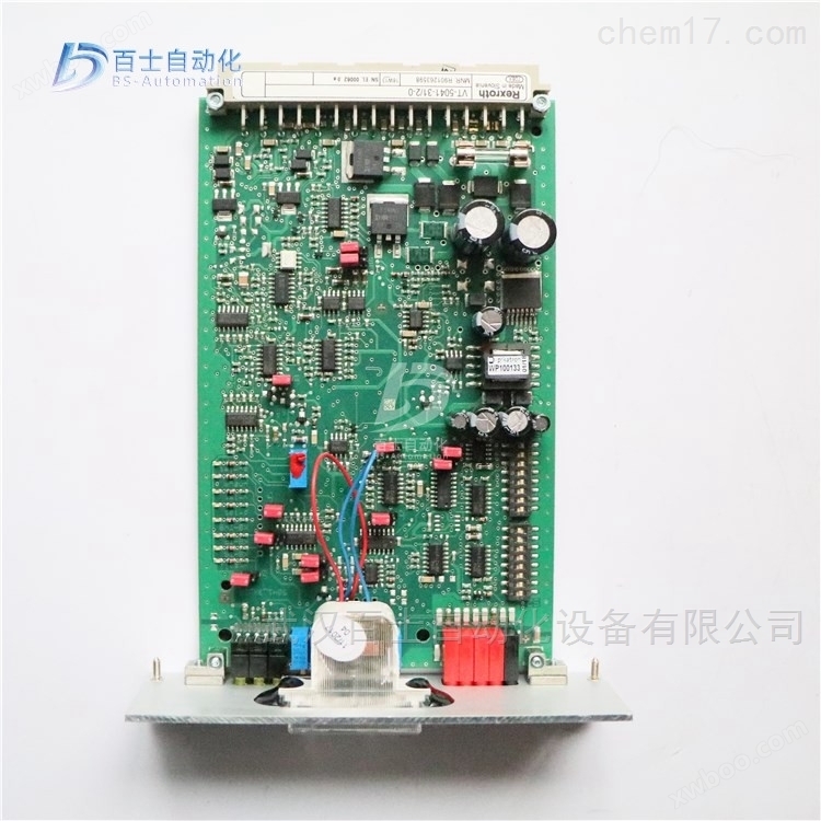
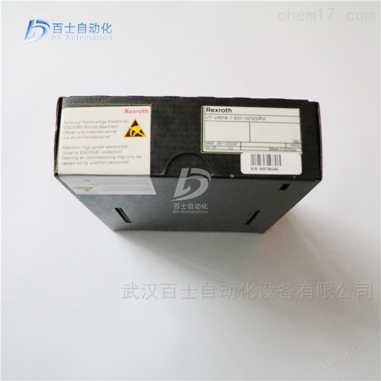
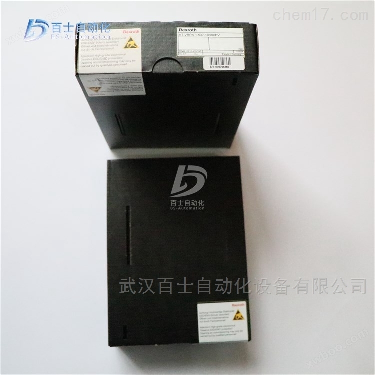
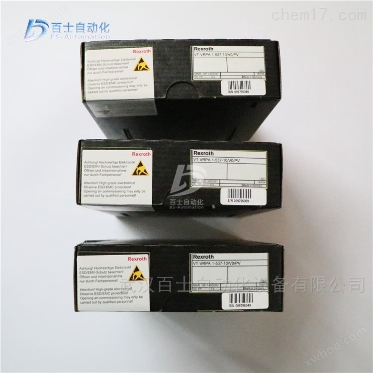

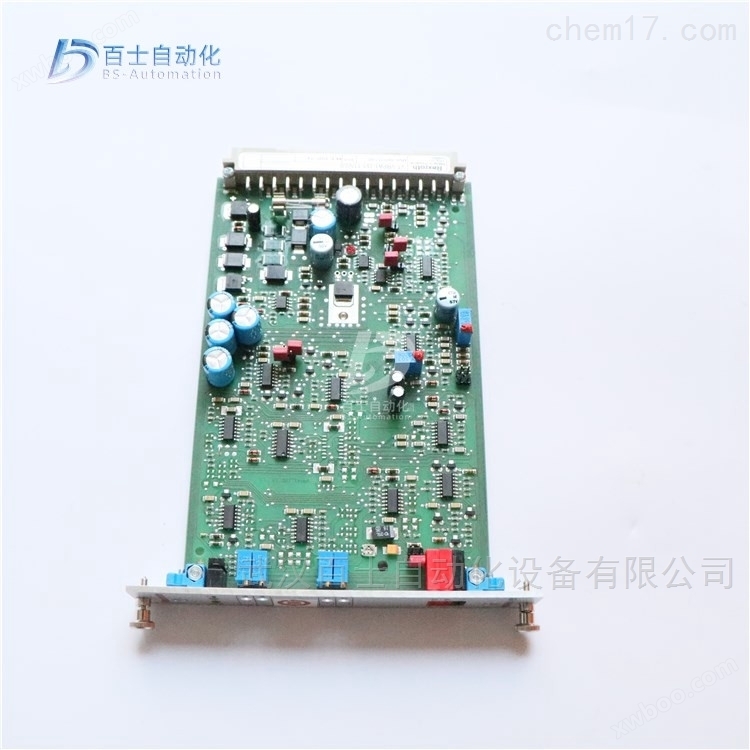
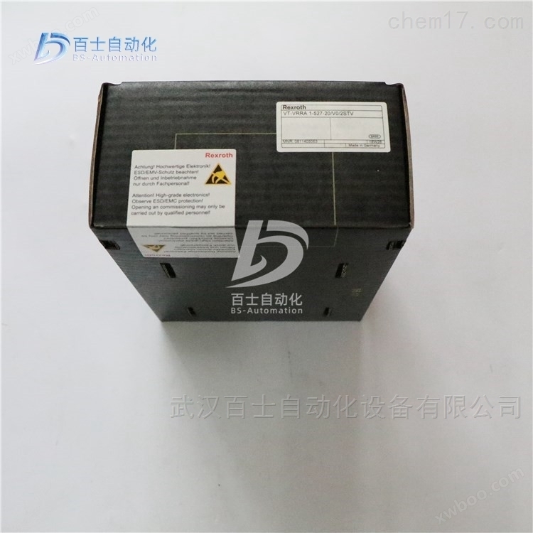
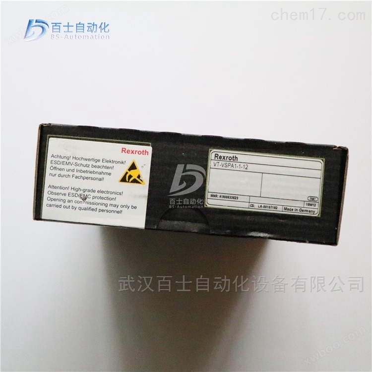
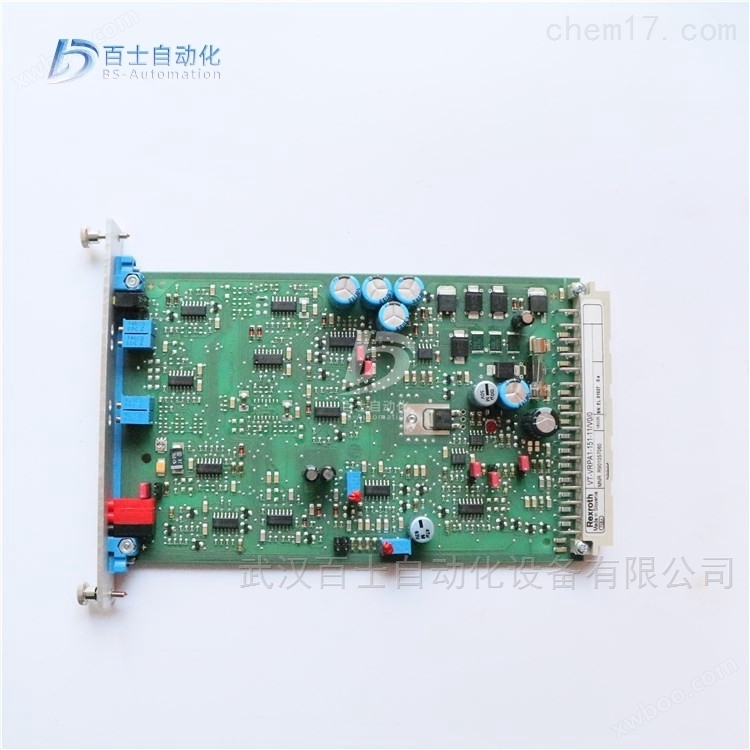
Piston pump proportional valve enlarged version R900579497 VT5035-17
NegotiableUpdate on 01/22
- Model
- Nature of the Manufacturer
- Producers
- Product Category
- Place of Origin
Overview
Piston pump proportional valve amplifier R900579497 VT5035-17, ReXROTH valve amplifier for regulating axial piston pump flow, ReXROTH piston pump proportional valve amplifier, ReXROTH piston pump proportional valve amplifier, ReXROTH piston pump proportional valve amplifier
Product Details
Piston pump proportional valve enlarged version R900579497 VT5035-17ReXROTH is a valve amplifier used to regulate the flow rate of axial piston pumps. It is a valve amplifier for proportional valves, a ReXROTH proportional valve amplifier, a ReXROTH plunger pump proportional valve amplification version, and a ReXROTH amplification version. Wuhan Baishi Automation Equipment Co., Ltd. specializes in selling products that are original from the factory and refuse high imitation and counterfeit goods. Customers can buy and use with peace of mind. *Common products available in stock, welcome new and old customers to inquire and purchase!


Structure and classification of hydraulic control valves
Divided into slide valve, nozzle baffle valve, and jet pipe valve
1 slide valve
Advantages: High power, large amplification factor, but high manipulation force, low sensitivity, and difficult processing.
Commonly used in the front-end stage.
Edge: work throttling edge, four sides, two sides, one side
Number of channels for slide valve: four-way, three-way
Opening type: The size relationship between the valve core shoulder and the valve body groove width when the valve is in zero position
Servo valves are generally zero opening or positive opening, while electro-hydraulic proportional valves are generally negative opening.
2. Nozzle baffle valve
Advantages: No friction pair, high sensitivity, fast response speed, low required control power
Disadvantage: Poor pollution resistance
Suitable for low power, commonly used for preamplifier.
Belonging to B-type hydraulic half bridge control, it consists of a fixed orifice and a variable orifice.
Category: Single nozzle baffle valve and dual nozzle baffle valve
The former has a simple structure, but can only be used in conjunction with asymmetric cylinders, and its characteristics are asymmetric
The latter has symmetrical characteristics and is mainly used to control symmetrical actuators
3. Jet tube valve
Composed of a flexible jet tube and a receiver. When the jet tube swings, the kinetic energy received on the left and right sides of the receiver is different, resulting in different converted pressure energy, achieving control of hydraulic power.
The force required to manipulate the jet tube is generally greater than that of the baffle, but the jet tube valve has good anti pollution properties. The application range is not as wide as that of nozzle baffle valves.
Taking slide valves as an example, the static characteristics of valves and the principles and derivation methods involved are applicable to hydraulic control valves of various structures.
Static nature:
The functional relationship between the load flow rate 2r, load pressure PL, and valve displacement XV of the valve in steady state, i.e. 2=f (xv, PL)
It reflects the working ability and performance of the valve itself.
The static characteristics of a valve can be obtained using either analytical or experimental methods. The general experimental method is more accurate,
But analytical methods are convenient for predicting the characteristics of valves.
Static characteristics can be represented by characteristic equations, characteristic curves, and characteristic coefficients (valve coefficients).
The valve coefficient can be obtained from the characteristic equation or characteristic curve, referring to the incremental variation characteristics of the valve at a given operating point.
Load sensing and pressure compensation technology for electro-hydraulic proportional multi way valve
Saving energy, reducing oil temperature, and improving control accuracy, while also ensuring that the synchronous action of several executing components does not interfere with each other during movement, load sensing and pressure compensation technology are now widely used in construction machinery. Load sensing and pressure compensation are very similar concepts, both of which use pressure changes caused by load changes to regulate pump or valve pressure and flow to meet system operating requirements. For a quantitative pump system, load sensing refers to directing the load pressure load sensing oil circuit to a remote pressure regulating relief valve. When the load is small, the relief valve's set pressure is also small; The load is large and the set pressure is also high, but there is always a certain overflow loss. The variable pump system introduces the load sensing oil circuit into the pump variable mechanism, so that the pump output pressure increases with the increase of load pressure (always a small fixed pressure difference), making the pump output flow equal to the actual required flow of the system, without overflow loss, and achieving energy saving. Pressure compensation is a guarantee measure taken to improve valve control performance. The load pressure behind the valve port is introduced into the pressure compensation valve, which adjusts the pressure in front of the valve port to maintain a constant pressure difference. This way, the flow regulation characteristics of the throttle port are only related to the opening of the valve port, and are not affected by the load pressure.
Piston pump proportional valve enlarged version R900579497 VT5035-17Rexroth REXROTH valve amplifier for regulating axial piston pump flow, Rexroth proportional valve amplifier, REXROTH plunger pump proportional valve amplification version, Rexroth amplification version
Rexroth REXROTH valve amplifier for regulating the flow rate of axial piston pumps using proportional valves
R910908873 ROUND BAR VT 5035 S13/R5
R900579497 VT5035-1X/
R900010926 VT5035S1X/R5
R978910921 VT5035-1X/SO43A-1631
R978034109 VT5035-1X/SO43A-1830
R901271027 VT-SR7-10/1NG500HS/VT13243
R900553971 VT-SR7-1X/0/A4VBV450HS
R900035095 VT-SR7-1X/0/A4VS.125HS
R900935936 VT-SR7-1X/0/A4VS.125HS
R978918867 VT-SR7-1X/0/A4VS.180HSSO43A-1608
R900035593 VT-SR7-1X/0/A4VS.250HS
R978917126 VT-SR7-1X/0/A4VS.250HSSO43A-1608
R900035612 VT-SR7-1X/0/A4VS.355HS
R900030717 VT-SR7-1X/0/A4VS.500HS
R978015962 VT-SR7-1X/0/A4VS.500HSSO43A-1608
R978915908 VT-SR7-1X/0/A4VS.500HSSO43A-1670
R978026931 VT-SR7-1X/0/EFF00270
R901162573 VT-SR7-1X/1/A4VS.1000HS
R900559948 VT-SR7-1X/1/A4VS.125HS
R900557769 VT-SR7-1X/1/A4VS.180HS
R900029274 VT-SR7-1X/1/A4VS.250HS
R900904507 VT-SR7-1X/1/A4VS.250HS1
R900579280 VT-SR7-1X/1/A4VS.355HS
R900020743 VT-SR7-1X/1/A4VS.40HS
R900029181 VT-SR7-1X/1/A4VS.500HS
R901211008 VT-SR7-1X/1/A4VS.71DS/VT12431A/U144
R900020742 VT-SR7-1X/1/A4VS.71HS
R900903708 VT-SR7-1X/1/A4VS.750HS
R987163695 VT-SR7-1X/A4VS.250HSSO026-693
R978056876 VT-SR7-1X/EFF00330
Composition of hydraulic transmission system
1. Hydraulic power components
A device that converts the mechanical energy of a power unit into hydraulic energy, providing pressure oil for the hydraulic transmission system and serving as its power source. For example, hydraulic pumps.
1.1 Hydraulic pump
The hydraulic pump is the power component of the hydraulic system, which converts the mechanical energy of the prime mover into the pressure energy of the liquid. It refers to the oil pump in the hydraulic system, which provides power to the entire hydraulic system. The structural forms of hydraulic pumps generally include gear pumps, vane pumps, and plunger pumps.
1.2 Gear pump
Gear pump is a pump that relies on two or more gears sealed in a housing to transport liquids through the change in working space volume generated during the meshing process. The concept of a gear pump is very simple, that is, its basic form is two gears of the same size meshing and rotating with each other in a tightly fitting housing. The interior of this housing is similar to an "8" shape, and two gears are installed inside, with the outer diameter and both sides of the gears tightly fitting with the housing. The material from the extruder enters the space between two gears at the suction port and fills it. It moves along the shell with the rotation of the teeth and is discharged when the two teeth mesh. The phenomenon of oil entrapment requires the gear pump to operate smoothly, and the meshing overlap of the gears must be greater than 1. Therefore, there are always two pairs of gears meshing simultaneously, and a portion of the oil is trapped between the closed chambers enclosed by the two pairs of gear teeth. This closed chamber begins to follow
The rotation of the gear gradually decreases and then gradually increases again. The decrease in the volume of the enclosed chamber will cause the trapped oil to be squeezed and generate high pressure, which will be squeezed out from the gaps, causing the oil to heat up and causing additional loads on the components. The increase in the volume of the enclosed chamber will also cause local vacuum, resulting in the separation of dissolved gases in the oil and the formation of gas pockets. These will all generate strong vibrations and noise, which is the phenomenon of fatigue in gear pumps.
Harm: When the radial unbalance force is large, it can cause the shaft to bend, the tooth tip to come into contact with the housing, and accelerate the wear of the bearing, reducing its service life.
Method for eliminating trapped oil: Usually, unloading slots are opened on both sides of the cover plate, so that when the volume of the closed chamber is small, it is connected to the oil pressure chamber through the unloading slot on the left, and when the volume increases, it is connected to the oil suction chamber through the unloading slot on the right.
1.3 Vane pump
A vane pump is a hydraulic machine that converts the mechanical energy of a power machine into water energy (potential energy, kinetic energy, pressure energy) through the rotation of the impeller.
When the rotor of the vane pump rotates, the tips of the blades are tightly attached to the inner surface of the stator under the action of centrifugal force and pressure oil. The working volume formed by the two blades and the inner surfaces of the rotor and stator first absorbs oil from small to large, and then discharges oil from large to small. When the blades rotate once, they complete two oil suction and discharge operations.
1.4 Piston pump
A plunger pump utilizes the reciprocating motion of a plunger within the pump cylinder to create a volume change between the plunger and the pump wall, allowing for repeated suction and discharge; A pump that releases liquid and increases its pressure.
A plunger pump is an important device in hydraulic systems. It relies on the reciprocating motion of the plunger in the cylinder body to change the volume of the sealed working chamber to achieve oil suction and pressure. Piston pumps have the advantages of high rated pressure, compact structure, high efficiency, and convenient flow regulation. They are widely used in high-pressure, high flow, and flow regulation applications, such as hydraulic presses, engineering machinery, and ships.

The elevated bridge type belt stacker is installed on a movable bridge that spans the material pile. There is an S-shaped unloading trolley on its stacking belt conveyor, which moves in the opposite direction to the bridge, allowing the stacking machine to stack materials at any point in the stack. This type of stacker is suitable for stacking materials with trapezoidal cross-sections, as well as for stacking materials in wave or horizontal layers.
A rake stacker, also known as a chain rake, is a device that can both stack and retrieve materials, mainly used for side stacking. Some chain rakes can also be reversed, that is, the rotation direction during stacking is opposite to that during material retrieval, and the material is sent to the downstream chain through the opening in the rake rod. The rake type stacker greatly improves its stacking capacity through the joint operation of the stacking belt and scraper installed in the chain scraper.
The overhead belt stacker for top stacking is used in the case where the pre homogenization stacking plant is located inside the factory building. The main feeding belt conveyor of the yard is connected to the roof truss through the roof of the factory building and linked to the overhead belt conveyor on the roof truss. The equipment used in this stacker is relatively simple. As long as an S-shaped belt unloading truck is installed on the overhead belt conveyor, materials can be directly stacked from the overhead belt. But it can only be used for herringbone or conical materials, and if wave shaped stacking is to be used, it will make the structure of the stacking equipment complex. Another disadvantage of it is that there is a large material gap. Therefore, this type of equipment is less commonly used in cement plants.
The rotary cantilever belt stacker is a type of stacker used for lateral stacking in pre homogenization yards. It mainly consists of two parts: one is the S-shaped belt unloading trolley connected to the main feeding belt conveyor in the yard, which is used to deliver materials to the stacking belt conveyor through the S-shaped turning of the feeding belt; The second is the cantilever stacking belt conveyor that extends horizontally above the material pile. The cantilever belt stacker can be fixed or a rotary cantilever belt stacker that rotates around the central axis. Its rotary motion is driven by an electric motor and can perform 360 rotations.
Automatic control refers to the unmanned control of the stacker, which monitors the working status of the stacker through a monitoring system. For example, the process operation control of the ore powder stacking machine should be automatically controlled under specific system control. The operator sits in the control room and can switch through the computer screen to understand various parameters of the stacker, the position of the cart, the operation of auxiliary systems and other components and systems; Set the operating parameters of the stacker, and use the automatic system to real-time understand the operating status and fault causes of the stacker, and be able to automatically record fault information.
Similar Product Recommend