-
E-mail
980227448@qq.com
-
Phone
15307180902
-
Address
Room 2003, 20th Floor, Building A, Luojiashan Building, No.7 Luojiashan Road, Hongshan District, Wuhan City
Product Categories
Wuhan Baishi Automation Equipment Co., Ltd
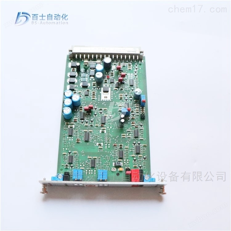
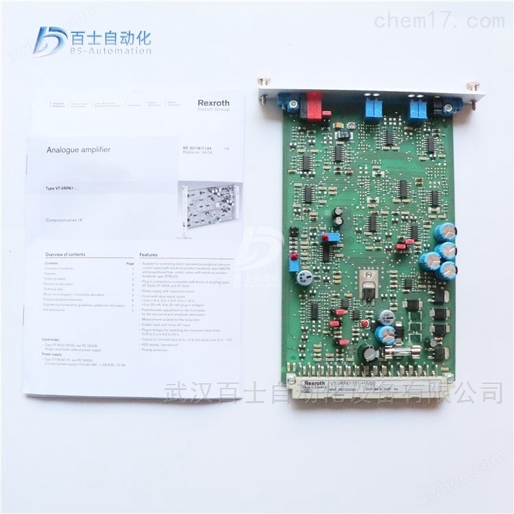
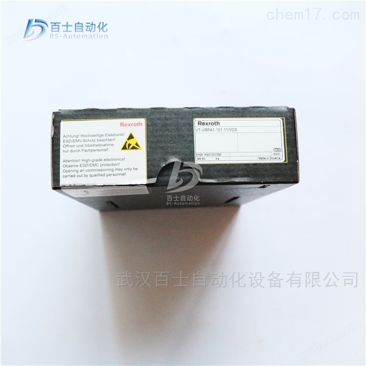
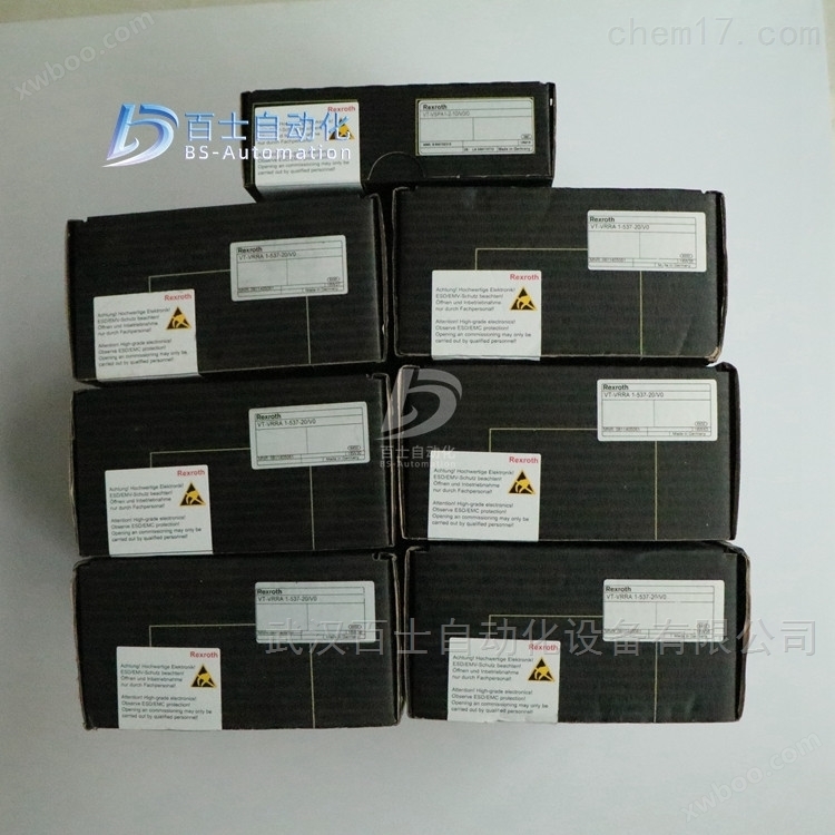
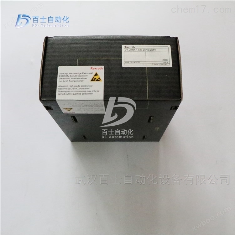
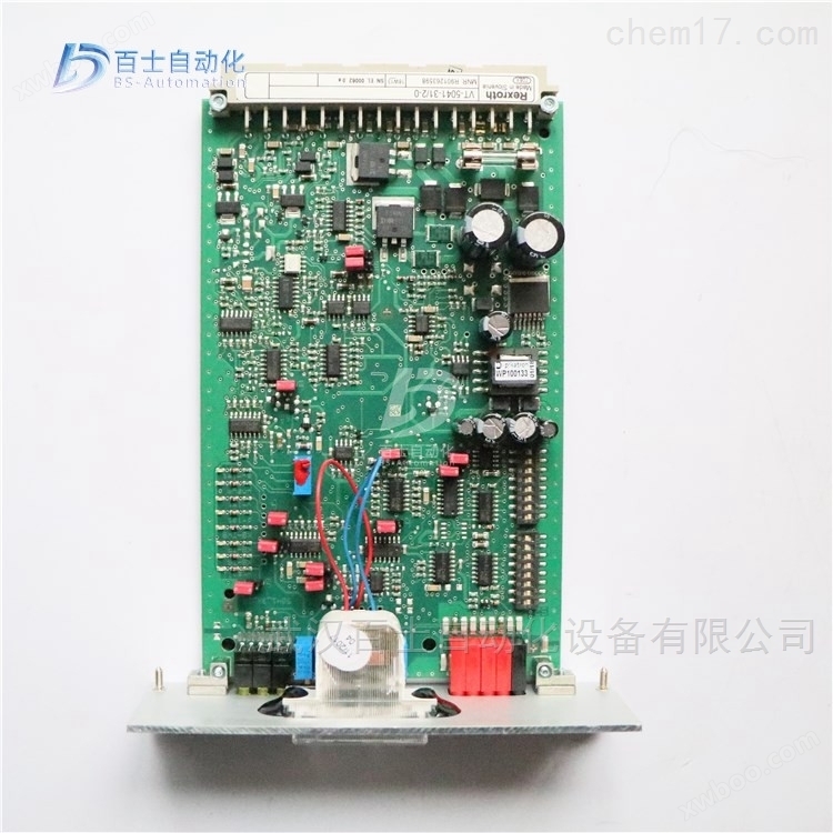
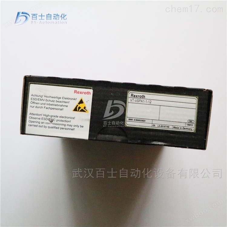
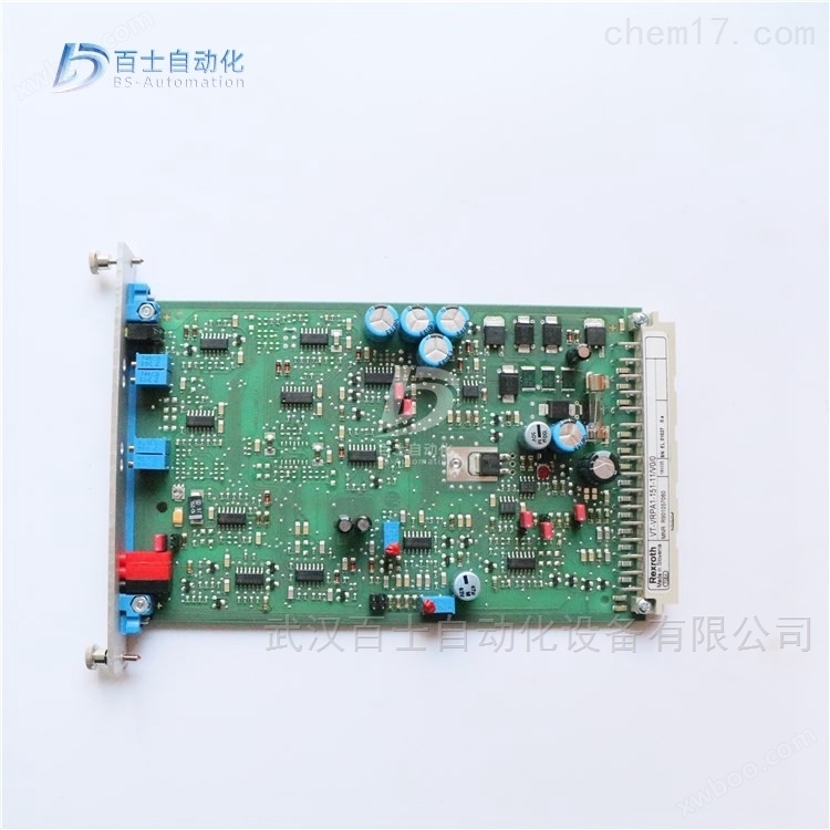
Rexroth enlarged version VT-MSPA2-1-1X/V0/0
NegotiableUpdate on 01/22
- Model
- Nature of the Manufacturer
- Producers
- Product Category
- Place of Origin
Overview
Rexroth enlarged version VT-MSPA2-1X/V0/0, German REXROTH enlarged version, Rexroth analog circuit enlarged version, REXROTH enlarged module, Rexroth proportional overflow valve enlarged version, REXROTH proportional valve enlarged version
Product Details
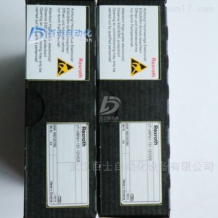
Rexroth enlarged version VT-MSPA2-1-1X/V0/0REXROTH amplification version, Rexroth analog circuit amplification version, REXROTH amplification module, Rexroth proportional overflow valve amplification version, REXROTH proportional valve amplification version, Wuhan Baishi Automation Equipment Co., Ltd. specializes in selling products that are original from the factory and refuse high imitation counterfeit goods. Customers can buy and use with peace of mind. *Common products available in stock, welcome new and old customers to inquire and purchase!


Power amplifier:
Gradually increasing the input signal causes the valve core to start moving, but due to the excessive coverage of the valve port, there is no flow output at the valve outlet. Only when the valve port opening is about 25% of the large opening, there is flow output at the valve outlet.
When the input signal reaches or exceeds 25% of the large input signal, the valve outlet has a flow output, which depends on the opening of the valve.
When there is no control signal, excessive valve port coverage can reduce leakage, but from a control perspective, it is not desirable to have too much dead zone.
dead zone compensation
However, by adjusting the dead zone compensation potentiometer on the power amplifier, the dead zone can be reduced.
Firstly, set 1% (0.1V) of the input signal as the dead zone and maintain it.
However, when the input signal exceeds this threshold, the power amplifier output will skip the threshold to move the spool to the edge of the dead zone. At this point, a flow rate corresponding to the input signal of 0.1-0.2 V will be generated, and then the valve port will gradually open as the input signal increases. However, when the input signal is about 7.5V, the valve opening will be large. In fact, from the start to the end of the valve core movement, the dead zone is also moving.
Gain adjustment
By adjusting the gain potentiometer to reduce the gain of the power amplifier, this situation can be corrected. A decrease in gain means that a higher input signal is required to produce a certain output. The gain can be set in such a way that when the input signal reaches a large value, the valve opening should also be large.
If the dead zone compensation is set too low, there will be a large dead zone interval when the valve core starts to move.
However, if the dead zone compensation is set too high, when the input signal reaches the national value of 0.1V-0.2V, the spool movement will cross the dead zone, indicating that the proportional valve is difficult to control small flow.
If the gain is set too low, the proportional valve opening may not be large when the input signal is large (note: in some cases, to limit the large flow of the proportional valve, the gain can be set lower)
If the gain setting is too high, the proportional valve opening will have already reached a large value before the input signal reaches a large value.
The third adjustment function is used to determine the speed of change in the output of the power amplifier when the input signal changes. This is also known as slope adjustment. When the slope function is not selected, turn off or guide
The input signal will generate a sudden change in the input signal or corresponding output signal. If the inertial load in the system suddenly starts and stops, it will cause system oscillation. However, when selecting the ramp function, the output of the power amplifier is Constant speed variation (increase and decrease).
Generally speaking, in order to achieve a large opening of the proportional valve, the large ramp time can be set to 5 seconds.
The monitoring points on the front panel of the power amplifier simplify the setting process. A monitoring point is used to indicate the input signal to the power amplifier, which is constrained by dead zone, gain, and ramp adjustments. The second monitoring point is used to indicate the displacement of the valve core (with feedback ratio)
Valve or feedback free proportional valve is used to indicate the output current (converted to constant voltage).
Proportional control technology is a transitional technology between switch control technology and servo control technology. It uses a proportional amplifier to control the proportional electromagnet, achieving continuous control of the comparative valve and achieving stepless adjustment of hydraulic system pressure, flow rate, and direction; However, when using a proportional directional valve for speed control, if the load changes, the speed of the actuator will be affected by the load changes (faster when the load is small and slower when the load is large); So in the system design, people introduced pressure compensators, which can keep the pressure difference at the proportional valve port constant, so that the speed of the actuator is not affected by load changes.
The hydraulic circuit for lifting and lowering the walking beam in a walking beam heating furnace at a certain steel plant. This circuit uses a proportional directional valve and inlet pressure compensation. Due to the presence of overload when the stepping beam descends, a balance valve is installed in the rodless chamber of the oil cylinder. After the spring of the pressure compensator is set (here it is a constant value), the pressure difference Δ p at the throttle port of the proportional valve is approximately constant, that is, the pressure difference Δ p before and after the inlet of the proportional directional valve remains constant. When the pressure difference before and after the throttle remains constant, the flow rate through the throttle is only proportional to the opening area of the throttle. For proportional directional valves, the opening area of the inlet throttle is related to the input current signal of the proportional directional valve, and is independent of changes in the load. That is to say, the oil supply flow rate Q of the lifting cylinder is only related to the input current signal of the proportional directional valve, and is not related to changes in the load.
Rexroth enlarged version VT-MSPA2-1-1X/V0/0German REXROTH amplification version, Rexroth analog circuit amplification version, REXROTH amplification module, Rexroth proportional overflow valve amplification version, REXROTH proportional valve amplification version
Rexroth REXROTH analog circuit amplification module, European version standard
0811405126 VT-MSPA1-508-10/V0
0811405127 VT-MSPA1-525-10/V0
0811405106 VT-MSPA2-525-10/V0
R901439037 VT-MSPA2-2X/A5/000/000
R900702060 VT-MSPA1-1-1X/V0/0
R901142355 VT-MSPA1-10-1X/V0
R901142360 VT-MSPA1-11-1X/V0/0
R901288145 VT-MSPA1-30-1X/V0/0
R901288142 VT-MSPA1-150-1X/V0/0
R901142366 VT-MSPA1-200-1X/V0/0
R900249810 VT-MSPA1-50-1X/V0
R901439034 VT-MSPA1-2X/A5/000/000
R901054016 VT-MSPA1-50-1X/V001
R901010980 VT-MSPA2-1-1X/V0/0
R901226865 VT-MSPA2-1-1X/V002/0 FOR TEST STAND EIV11
R901348140 VT-MSPA2-1-1X=V0/0
R901061664 VT-MSPA2-200-1X/V0/0
R900537344 VT11131-1X/
R900030647 VT11132-1X/
R900010960 VT11013-10
R900211788 VT11118-1X/
R900211788 VT11118-10
R900211788 VT11118-11
R901280829 VT11118-1X=
R900010938 VT11015-1X/
R900010938 VT11015-11
R900019681 VT11017-1X/
R900019681 VT11017-11
R901463732 SERVO-AMPLIFIER AN422V05-08-0-1
R901197784 VT-MSRA1-1-1X/V0/0
R901386328 VT-MSRA1-1-1X/V001
Rexroth REXROTH digital enlarged version, European version standard
R901077297 VT-VSPD-1-2X/V0/0-0-1
R901161533 VT-VSPD-1-2X/V0/1-0-1
Rexroth REXROTH valve amplifier with electric position feedback proportional valve
Rexroth REXROTH Analog Amplification Module
R900752430 VT-MRMA1-1-1X/V0/0
R900779644 VT-MRPA1-100-1X/V0/0
R901080965 VT-MRPA1-150-1X/V0/0
Plastic machinery is a general term for various types of machinery and devices used in the plastic processing industry. Some universal machinery and equipment for transporting, separating, crushing, grinding, and drying fluids and solids also play an important role in the plastic processing industry, so they are often listed as plastic machinery.
According to the production process of plastic products, plastic machinery can be divided into four categories: plastic mixing machinery, plastic molding machinery, plastic secondary processing machinery, and plastic processing auxiliary machinery or devices. Plastic mixing machinery is used for the manufacturing of various forms of plastic mixing materials, including kneading machines, plasticizing machines (open and internal mixers), granulators, screening machines, crushers, and grinders. Plastic molding machinery, also known as plastic primary processing machinery, is used for the molding of plastic semi-finished or finished products, including compression molding machines, injection molding machines, extruders, blow molding machines, calendering machines, rolling molding machines, foaming machines, etc. Plastic secondary processing machinery is used for the reprocessing and post-treatment of plastic semi-finished or finished products, including thermoforming machines, welding machines, heat sealing machines, hot stamping machines, vacuum evaporation machines, flocking machines, printing machines, etc. Metal processing machines are also commonly used for secondary processing of plastics. Plastic processing auxiliary machinery or devices are used to rationalize the plastic processing process, including automatic measuring and feeding devices, automatic scrap recycling devices, automatic removal devices for injection molded products, rapid replacement devices for injection molds, injection mold cooling machines, automatic thickness measuring devices, and raw material conveying and storage equipment. These types of auxiliary machinery or devices have become a part of modern plastic processing automation.
Injection molding machine is used to inject molten plastic into a mold, and after cooling, it becomes a product. It has a wide range of applications and is used in different places depending on the type of plastic used. Injection molding machine is a widely used processing machinery in the plastic processing industry, and not only can a large number of products be directly produced by injection molding machine, but it is also a key equipment in the injection pull blowing process.
Blow molding is a common method for manufacturing hollow thermoplastic products, mainly consisting of tubular membranes and hollow containers. Blow molding machine can plasticize pre formed products by heating, and then enter the mold for blow molding. This method is mainly used for high-speed and high-yield production of PET bottles and BOPP bottles, that is, two-step process; Blow molding can also be combined with injection molding technology to become an injection pull blow integrated machine, which is also a common method for producing containers in PET; Blow molding technology can also be combined with extrusion technology, and extrusion blow molding equipment has a wider range of adaptability and can produce a wider variety of products, including multi-layer composite films and various polyolefin hollow containers, which are widely used in the food and cosmetics industry
The blown film machine heats and melts plastic particles before blowing them into a thin film. There are many types of blown film machines, including PE, POF, and so on. The blown film machine produces films suitable for various high-end film packaging. This type of film, due to its good barrier properties, preservation, moisture resistance, frost resistance, oxygen barrier, and oil resistance, can be widely used for light and heavy packaging. Such as various fresh fruits, meat products, Pickled vegetables, fresh milk, liquid drinks, etc.
In plastic machinery, the rolling mill is usually combined with leading devices such as material conveying, screening, metering, kneading, and plasticizing, as well as subsequent devices such as guiding, pulling, embossing, cooling, thickness measurement, coiling, and cutting, and transmission, monitoring, and heating devices to form a complete rolling production line, producing soft and hard films, sheets, artificial leather, wallpaper, and flooring rolls.

proportional control valve
A valve that uses a proportional electromagnet (or torque motor) to convert input signals into force or mechanical displacement of the valve, so that the output (pressure, flow) of the valve is continuously and proportionally controlled according to its input quantity.
There are several types of proportional valves used on site in large steel mills, including servo proportional control valves, proportional control valves, electro-hydraulic proportional control valves, proportional valves, and servo valves.
1. 4WRD E. proportional servo control valve (high-frequency response valve)
Structure and Function
The 4WRDE type valve is a three-stage high-frequency directional valve. This valve can be used for open-loop control or closed-loop regulation of the size and direction of fluid flow, but is mainly used in closed-loop regulation circuits.
The valve is mainly composed of the following parts:
The secondary pilot control valve consists of a torque motor (1), a hydraulic amplifier (5) composed of a nozzle baffle valve, and a valve core liner assembly (6) used as a flow amplification stage (to control the third stage (7)).
The third level (7) is used for flow control.
3. Inductive displacement sensor (8), connected to the magnetic core (9) of the third stage main valve core (10)
Realize valve closed-loop control signal logic connection, position detection system feedback, and pilot valve control through built-in electronic amplifier.
The differential voltage obtained by comparing the given value with the actual value is amplified by an electronic controller and transmitted as a control deviation to the first stage of the valve. This signal drives the baffle (2) between the two control nozzles (3.1, 3.2), thus creating a pressure difference between the two control chambers (11.1.11.2). The control valve core (4) is therefore pushed and flows through the corresponding liquid flow to the spring chamber (12.1 or 12.2). The valve core (10) and the displacement sensor (8) with magnetic core (9) move straight until the actual value and the given value signal are equal again. Under controlled conditions; The main valve core (10) is always maintained at the position corresponding to the given value.
The spool stroke is proportional to the given value. By adjusting the position of the valve core (10) relative to the control edge (13), a corresponding valve opening proportional to the flow rate is formed.
The dynamic characteristics of the valve are optimized through an electronic amplifier. The electronic amplifier is built into the valve (oscillator, demodulator)
Zero point adjustment is pre-set by the manufacturer and can be adjusted within 10% of the nominal range through closed-loop control of the potentiometer inside the electronic amplifier. Remove the plug at the end of the valve cover to operate the built-in closed-loop electronic amplifier.
2. 4WREE proportional control valve
1. Structure and functional principles
The two position four-way and three position four-way proportional directional valves are directly controlled and have a plate structure; Operated by proportional electromagnetic, proportional electromagnetic With a central thread, the ring can be disassembled separately, and electromagnetic control can be achieved through an external amplifier (WRA type) or a built-in amplifier (WRAE type).
Structure:
This valve consists of the following parts:
Valve body with installation bottom (1)
Control valve core (2) with springs (3 and 4)
Electromagnets with central thread (5 and 6)
Displacement sensor (7)
Optional with built-in amplifier (8)
Mechanical zero adjustment (9),
Working principle:
When the electromagnets (5 and 6) are not charged, the centering springs (3 and 4) keep the control valve core (2) in the neutral position
After the proportional electromagnetic coil is energized, it will directly push the control valve core (2). For example, when the control electromagnetic coil 'b' (6) is excited, the control valve core (2) is pushed to the left, and the displacement is proportional to the input electrical signal. At this time, the P to A and B to T ports communicate with the valve body through the throttle formed by the valve core and the valve body, and have progressive flow characteristics. Electromagnetic coil (6) power loss control The valve core (2) is pushed back to the center position by the centering spring (3).
In the event of a loss of power to the electromagnet, the valve core (2) remains in the mechanical neutral position under the action of the electromagnetic reset spring. This is not related to the hydraulic center position for the valve core with the function symbol "V"! When the valve is closed for closed-loop control, the spool is placed in the hydraulic neutral position.
It is necessary to avoid completely draining the oil in the return line, and if necessary, install a back pressure valve (back pressure of about 2 bar) in the circuit.
3. 4WR... type proportional control valve
3. Structure and functional principles
Pilot control valve model 3DREP 6... This pilot valve is a three-way pressure reducing valve controlled by a proportional solenoid. Its function is to convert an input electrical signal into a pressure output signal proportional to it, which can be used for the control of all 4WRZ... and 5WR... proportional valves.
The proportional electromagnet is an adjustable, wet DC electromagnetic structure with a central thread, and the coil can be disassembled separately; Electromagnetic control can be achieved through external amplifiers (WRZ type) or built-in amplifiers (WRZE type).
Structure:
The valve mainly consists of the following parts:
(1) Shell with installation bottom surface (1);
(2) Control valve core (2) equipped with pressure measuring pistons (3 and 4);
(3) Electromagnetic coil with central thread (5 and 6);
(4) Optional with built-in amplifier (7)
Working principle:
(1) When the electromagnets (5 and 6) are not charged, the centering spring keeps the control valve core (2) in the neutral position;
(2) After the proportional electromagnet is energized, it will directly push the control valve core (2), for example: the electromagnetic "a" (5) is excited;
(3) The control valve core (2) and pressure measuring piston (3) are pushed to the left;
(4) Displacement is proportional to the input electrical signal.
At this point, the P and B ports, as well as the A and T ports, are connected through the throttle port 1 formed by the valve core and valve body, and the throttling characteristics are progressive. If the electromagnet (5) loses power, the control valve core (2) is pushed back to the neutral position by the spring. In the middle position of the pilot valve, ports A, B, and T are connected, which also means that the oil can be directly returned to the tank from here.
Pilot operated proportional directional valve, models 4WRZ. and 5WRZ., 4WRZ. valve is a pilot operated, proportional solenoid valve
A four-way directional valve that controls the direction and magnitude of fluid flow.
Structure:
The valve mainly consists of the following parts:
(1) Equipped with proportional electromagnetic Pilot control valve (9) for (5 and 6)
(2) Main valve (10) equipped with main valve core (11) and centering spring (12)
Working principle:
(1) When the electromagnets (5 and 6) are not charged, the centering spring (12) keeps the main valve core (11) in the neutral position.
(2) The action of the main valve core (11) is controlled by the pilot valve (9) - it is indirectly pushed proportionally by the electromagnet "b '(6). Firstly, the control valve core (2) is pushed to the right, and the control oil enters the control chamber (13) through the pilot valve (9), and pushes the main valve core (11) in proportion to the input signal. At this time, the P port, A port, B port, and T port are connected through the throttle port formed by the valve core and valve body, and the throttle characteristic is gradual.
(3) The control oil required for the pilot valve can be supplied through P port or X port.
(4) If the electromagnet (6) loses power, the control valve core (2) and the main valve core (11) will return to the neutral position.
(5) Depending on the position of the main valve core, P port is connected to A port, B port is connected to T port (R), or P port is connected to B port, A port is connected to T port (R). Optional protective cover for manual emergency operation (14 and 15), which allows the pilot valve core (2) to move in the absence of electromagnetic power.
Similar Product Recommend