-
E-mail
980227448@qq.com
-
Phone
15307180902
-
Address
Room 2003, 20th Floor, Building A, Luojiashan Building, No.7 Luojiashan Road, Hongshan District, Wuhan City
Product Categories
Wuhan Baishi Automation Equipment Co., Ltd
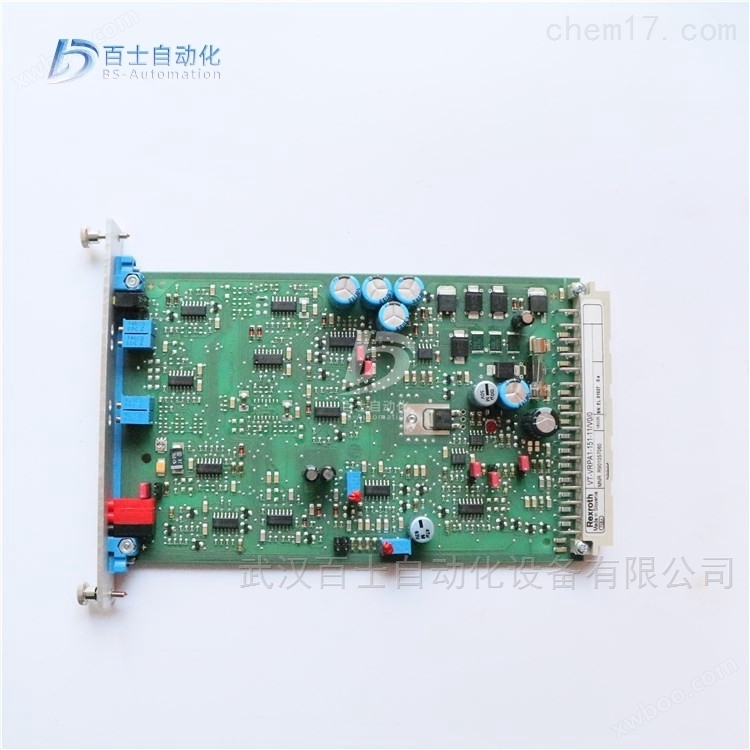
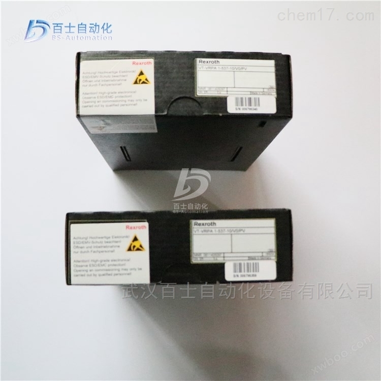
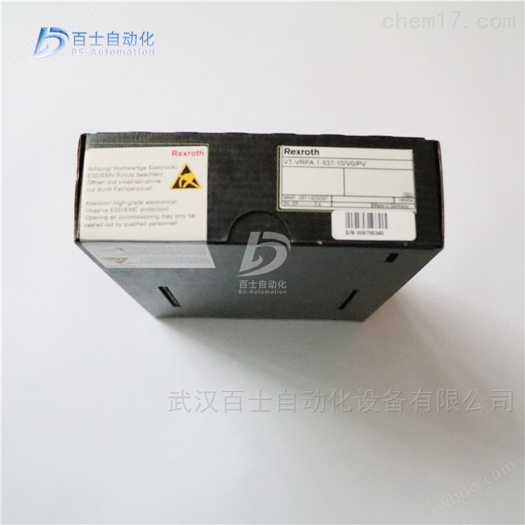
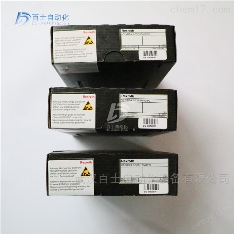
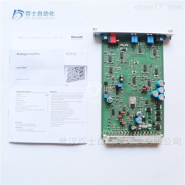
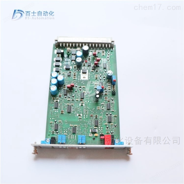
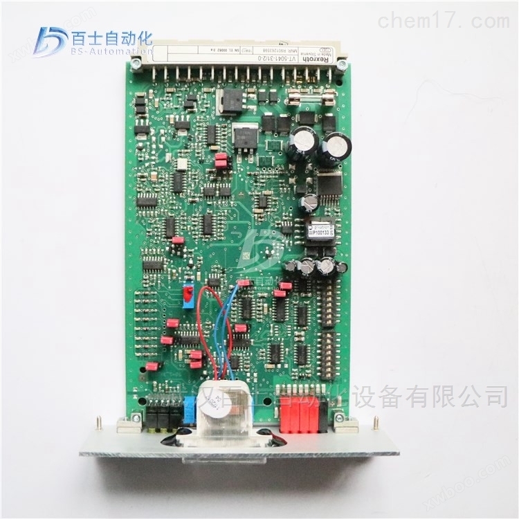
Rexroth enlarged module VT-MSPA2-2X/A5/000/000
NegotiableUpdate on 01/22
- Model
- Nature of the Manufacturer
- Producers
- Product Category
- Place of Origin
Overview
Rexroth amplification module VT-MSPA2-2X/A5/000/000 R901439037, REXROTH analog circuit amplification version, Rexroth amplification version, REXROTH proportional directional valve amplification version, Rexroth proportional pressure valve amplification version
Product Details
Rexroth enlarged module VT-MSPA2-2X/A5/000/000R901439037, REXROTH analog circuit amplification version, ReXROTH amplification version, REXROTH proportional reversing valve amplification version, ReXROTH proportional pressure valve amplification version, Wuhan Baishi Automation Equipment Co., Ltd. specializes in selling products that are original from the factory and refuse high imitation and counterfeit goods. Customers can buy and use with peace of mind. *Common products available in stock, welcome new and old customers to inquire and purchase!


A hydraulic amplifier utilizes the principle of throttling to control the fluid flow or pressure to the actuator using input displacement (angle) signals, and is a mechanical hydraulic conversion device. Due to the low input power and high output power of the control valve, it is also a type of power amplifier component. It, together with a converter and feedback mechanism, forms a synchronous valve and is the core component of the servo system.
In hydraulic servo systems, hydraulic amplifiers typically drive the actuator with their high output power flow, and the actuator converts hydraulic energy into mechanical energy to drive the load.
A hydraulic amplifier can be composed of a single or multiple (usually two) hydraulic amplifiers, referred to as single-stage or multi-stage hydraulic amplifiers.
The basic hydraulic amplification components mainly include slide valves, nozzle baffle valves, and jet tube valves. Among them, slide valves and jet tube valves can be used as single-stage hydraulic amplifiers, with the former being the most common; The nozzle baffle valve is generally used as a preamplifier for multi-stage amplifiers.
The slide valve and nozzle baffle valve are both throttling amplifiers, which control fluid dynamics by changing the impedance of the throttle hole on the liquid flow circuit, but they have different forms of throttle holes. Jet tube valve is a type of diversion component.
A hydraulic amplifier can be a hydraulic servo valve or a servo variable pump (with angular displacement as input and flow rate as output). This chapter mainly introduces hydraulic servo valves.
proportional control valve
A valve that uses a proportional electromagnet (or torque motor) to convert input signals into force or mechanical displacement of the valve, so that the output (pressure, flow) of the valve is continuously and proportionally controlled according to its input quantity.
There are several types of proportional valves used on site in large steel mills, including servo proportional control valves, proportional control valves, electro-hydraulic proportional control valves, proportional valves, and servo valves.
1. 4WRD E. proportional servo control valve (high-frequency response valve)
Structure and Function
The 4WRDE type valve is a three-stage high-frequency directional valve. This valve can be used for open-loop control or closed-loop regulation of the size and direction of fluid flow, but is mainly used in closed-loop regulation circuits.
The valve is mainly composed of the following parts:
The secondary pilot control valve consists of a torque motor (1), a hydraulic amplifier (5) composed of a nozzle baffle valve, and a valve core liner assembly (6) used as a flow amplification stage (to control the third stage (7)).
The third level (7) is used for flow control.
3. Inductive displacement sensor (8), connected to the magnetic core (9) of the third stage main valve core (10)
Realize valve closed-loop control signal logic connection, position detection system feedback, and pilot valve control through built-in electronic amplifier.
The differential voltage obtained by comparing the given value with the actual value is amplified by an electronic controller and transmitted as a control deviation to the first stage of the valve. This signal drives the baffle (2) between the two control nozzles (3.1, 3.2), thus creating a pressure difference between the two control chambers (11.1.11.2). The control valve core (4) is therefore pushed and flows through the corresponding liquid flow to the spring chamber (12.1 or 12.2). The valve core (10) and the displacement sensor (8) with magnetic core (9) move straight until the actual value and the given value signal are equal again. Under controlled conditions; The main valve core (10) is always maintained at the position corresponding to the given value.
The spool stroke is proportional to the given value. By adjusting the position of the valve core (10) relative to the control edge (13), a corresponding valve opening proportional to the flow rate is formed.
The dynamic characteristics of the valve are optimized through an electronic amplifier. The electronic amplifier is built into the valve (oscillator, demodulator)
Zero point adjustment is pre-set by the manufacturer and can be adjusted within 10% of the nominal range through closed-loop control of the potentiometer inside the electronic amplifier. Remove the plug at the end of the valve cover to operate the built-in closed-loop electronic amplifier.
2. 4WREE proportional control valve
1. Structure and functional principles
The two position four-way and three position four-way proportional directional valves are directly controlled and have a plate structure; Operated by proportional electromagnetic, proportional electromagnetic With a central thread, the ring can be disassembled separately, and electromagnetic control can be achieved through an external amplifier (WRA type) or a built-in amplifier (WRAE type).
Structure:
This valve consists of the following parts:
Valve body with installation bottom (1)
Control valve core (2) with springs (3 and 4)
Electromagnets with central thread (5 and 6)
Displacement sensor (7)
Optional with built-in amplifier (8)
Mechanical zero adjustment (9),
Working principle:
When the electromagnets (5 and 6) are not charged, the centering springs (3 and 4) keep the control valve core (2) in the neutral position
After the proportional electromagnetic coil is energized, it will directly push the control valve core (2). For example, when the control electromagnetic coil 'b' (6) is excited, the control valve core (2) is pushed to the left, and the displacement is proportional to the input electrical signal. At this time, the P to A and B to T ports communicate with the valve body through the throttle formed by the valve core and the valve body, and have progressive flow characteristics. Electromagnetic coil (6) power loss control The valve core (2) is pushed back to the center position by the centering spring (3).
In the event of a loss of power to the electromagnet, the valve core (2) remains in the mechanical neutral position under the action of the electromagnetic reset spring. This is not related to the hydraulic center position for the valve core with the function symbol "V"! When the valve is closed for closed-loop control, the spool is placed in the hydraulic neutral position.
It is necessary to avoid completely draining the oil in the return line, and if necessary, install a back pressure valve (back pressure of about 2 bar) in the circuit.
3. 4WR... type proportional control valve
3. Structure and functional principles
Pilot control valve model 3DREP 6... This pilot valve is a three-way pressure reducing valve controlled by a proportional solenoid. Its function is to convert an input electrical signal into a pressure output signal proportional to it, which can be used for the control of all 4WRZ... and 5WR... proportional valves.
The proportional electromagnet is an adjustable, wet DC electromagnetic structure with a central thread, and the coil can be disassembled separately; Electromagnetic control can be achieved through external amplifiers (WRZ type) or built-in amplifiers (WRZE type).
Structure:
The valve mainly consists of the following parts:
(1) Shell with installation bottom surface (1);
(2) Control valve core (2) equipped with pressure measuring pistons (3 and 4);
(3) Electromagnetic coil with central thread (5 and 6);
(4) Optional with built-in amplifier (7)
Working principle:
(1) When the electromagnets (5 and 6) are not charged, the centering spring keeps the control valve core (2) in the neutral position;
(2) After the proportional electromagnet is energized, it will directly push the control valve core (2), for example: the electromagnetic "a" (5) is excited;
(3) The control valve core (2) and pressure measuring piston (3) are pushed to the left;
(4) Displacement is proportional to the input electrical signal.
At this point, the P and B ports, as well as the A and T ports, are connected through the throttle port 1 formed by the valve core and valve body, and the throttling characteristics are progressive. If the electromagnet (5) loses power, the control valve core (2) is pushed back to the neutral position by the spring. In the middle position of the pilot valve, ports A, B, and T are connected, which also means that the oil can be directly returned to the tank from here.
Pilot operated proportional directional valve, models 4WRZ. and 5WRZ., 4WRZ. valve is a pilot operated, proportional solenoid valve
A four-way directional valve that controls the direction and magnitude of fluid flow.
Structure:
The valve mainly consists of the following parts:
(1) Equipped with proportional electromagnetic Pilot control valve (9) for (5 and 6)
(2) Main valve (10) equipped with main valve core (11) and centering spring (12)
Working principle:
(1) When the electromagnets (5 and 6) are not charged, the centering spring (12) keeps the main valve core (11) in the neutral position.
(2) The action of the main valve core (11) is controlled by the pilot valve (9) - it is indirectly pushed proportionally by the electromagnet "b '(6). Firstly, the control valve core (2) is pushed to the right, and the control oil enters the control chamber (13) through the pilot valve (9), and pushes the main valve core (11) in proportion to the input signal. At this time, the P port, A port, B port, and T port are connected through the throttle port formed by the valve core and valve body, and the throttle characteristic is gradual.
(3) The control oil required for the pilot valve can be supplied through P port or X port.
(4) If the electromagnet (6) loses power, the control valve core (2) and the main valve core (11) will return to the neutral position.
(5) Depending on the position of the main valve core, P port is connected to A port, B port is connected to T port (R), or P port is connected to B port, A port is connected to T port (R). Optional protective cover for manual emergency operation (14 and 15), which allows the pilot valve core (2) to move in the absence of electromagnetic power.
Rexroth enlarged module VT-MSPA2-2X/A5/000/000R901439037, REXROTH analog circuit amplification version, Rexroth amplification version, REXROTH proportional directional valve amplification version, Rexroth proportional pressure valve amplification version
Rexroth REXROTH analog circuit amplification module, European version standard
0811405126 VT-MSPA1-508-10/V0
0811405127 VT-MSPA1-525-10/V0
0811405106 VT-MSPA2-525-10/V0
R901439037 VT-MSPA2-2X/A5/000/000
R900702060 VT-MSPA1-1-1X/V0/0
R901142355 VT-MSPA1-10-1X/V0
R901142360 VT-MSPA1-11-1X/V0/0
R901288145 VT-MSPA1-30-1X/V0/0
R901288142 VT-MSPA1-150-1X/V0/0
R901142366 VT-MSPA1-200-1X/V0/0
R900249810 VT-MSPA1-50-1X/V0
R901439034 VT-MSPA1-2X/A5/000/000
R901054016 VT-MSPA1-50-1X/V001
R901010980 VT-MSPA2-1-1X/V0/0
R901226865 VT-MSPA2-1-1X/V002/0 FOR TEST STAND EIV11
R901348140 VT-MSPA2-1-1X=V0/0
R901061664 VT-MSPA2-200-1X/V0/0
R900537344 VT11131-1X/
R900030647 VT11132-1X/
R900010960 VT11013-10
R900211788 VT11118-1X/
R900211788 VT11118-10
R900211788 VT11118-11
R901280829 VT11118-1X=
R900010938 VT11015-1X/
R900010938 VT11015-11
R900019681 VT11017-1X/
R900019681 VT11017-11
R901463732 SERVO-AMPLIFIER AN422V05-08-0-1
R901197784 VT-MSRA1-1-1X/V0/0
R901386328 VT-MSRA1-1-1X/V001
Injection molding machine, also known as injection molding machine or injection machine. It is the main molding equipment that uses plastic molds to produce various shapes of plastic products from thermoplastic or thermosetting plastics. Divided into vertical, horizontal, and fully electric types. Injection molding machines can heat plastic, apply high pressure to molten plastic, and inject it to fill the mold cavity.
compose
Injection molding machines are usually composed of injection systems, mold clamping systems, hydraulic transmission systems, electrical control systems, lubrication systems, heating and cooling systems, safety monitoring systems, etc.
Injection system
The function of the injection system: The injection system is one of the main components of the injection molding machine, generally in three main forms: plunger type, screw type, and screw pre molded plunger injection type. The screw type is widely used. Its function is to heat and plasticize a certain amount of plastic within a specified time in one cycle of the injection molding machine, and then inject the molten plastic into the mold cavity through a screw under a certain pressure and speed. After injection, maintain the shape of the molten material injected into the mold cavity.
Composition of injection system: The injection system consists of a plasticizing device and a power transmission device.
The plasticizing device of the screw injection molding machine mainly consists of a feeding device, a material cylinder, a screw, a glue passing component, and a nozzle part. The power transmission device includes an injection cylinder, an injection seat moving cylinder, and a screw drive device (melt adhesive motor).
Mold closing system
The function of the mold closing system: The function of the mold closing system is to ensure the closure, opening, and ejection of the product. At the same time, after the mold is closed, sufficient locking force is supplied to the mold to resist the pressure generated by the molten plastic entering the mold cavity, prevent the mold from opening and causing poor product quality.
The composition of the mold clamping system: The mold clamping system mainly consists of a clamping device, a machine winch, a mold adjustment mechanism, an ejection mechanism, front and rear fixed templates, a moving template, a mold clamping oil cylinder, and a safety protection mechanism.
hydraulic system
The function of the hydraulic transmission system is to provide power for various actions required by the injection molding machine according to the process requirements, and to meet the pressure, speed, temperature, and other requirements of each part of the injection molding machine. It is mainly composed of various hydraulic components and hydraulic auxiliary components, among which the oil pump and motor are the power sources of the injection molding machine. Various valves control oil pressure and flow to meet the requirements of injection molding processes.
Electrical Control
Reasonable coordination between the electrical control system and the hydraulic system can meet the process requirements (pressure, temperature, speed, time) and various program actions of the injection machine. It is mainly composed of electrical appliances, electronic components, instruments (see the bottom right figure), heaters, sensors, etc. There are generally four control modes: manual, semi-automatic, fully automatic, and adjustable.

slipway for Combined Machine Tools
The power slide table is a universal component of the combination machine tool, on which cutting heads for various process purposes can be configured. The hydraulic power slide table of machine tools can achieve various working cycles, among which a typical working cycle is: fast forward → first working forward → second working forward → dead stop iron stop → fast retreat → stop. Differential connection of hydraulic cylinders to achieve rapid movement; The system adopts a pressure limiting variable vane pump for oil supply; Use stroke valves and hydraulic control sequence valves to switch between fast forward and working in; The electro-hydraulic directional valve enables differential connection between the hydraulic cylinder and the variable displacement pump to achieve rapid movement;
(1) Fast forward and press the start button. The pilot solenoid directional valve 1YA of the three position five way electro-hydraulic directional valve 5 is powered on, causing the valve core to move to the right and enter the working state in the left position. Use a two position two-way electromagnetic directional valve to achieve speed switching between the first and second working inputs.
(2) At the end of the fast forward stroke, the stop iron on the slide table presses the travel valve. Use stroke valves and hydraulic control sequence valves to switch between fast forward and working in; Use a two position two-way electromagnetic directional valve to achieve speed switching between the first and second working inputs.
(3) In order to ensure the dimensional accuracy of the second feed, a dead stop iron was used to limit the position.
(4) When the dead stop iron is stopped at the end of the second working feed of the power slide table, the hydraulic cylinder stops moving and the system pressure further increases. When it reaches the set value of pressure relay 15, after a delay of the time relay, an electrical signal is sent out again to retract the slide table. Before the delay action of the time relay, the sliding table stays at the position limited by the dead stop block.
(5) After the fast return time relay sends an electrical signal, the electro-hydraulic reversing valve works in the right position. At this point, the system pressure is low, and the output flow of variable pump 2 is high, causing the power slide table to quickly retract. Due to the fact that the area of the piston rod is approximately half that of the piston, the forward and backward speeds of the power slide are roughly equal.
(6) When the power slide returns to its original position, the stop block presses the travel switch, the electro-hydraulic directional valve is in the neutral position, the power slide stops moving, and the variable pump unloads.
Introduction to Hydraulic Systems and Hydraulic Components
1、 The composition of hydraulic system: power part, control part, execution part, auxiliary device hydraulic pump; Used to convert mechanical energy into liquid pressure energy, sometimes accumulator is also used as an emergency or auxiliary power source
Various pressure, flow, direction and other control valves; Used to control the movement speed, direction, and force of the executing components, as well as to achieve overload protection, program control, etc
Hydraulic cylinders, hydraulic motors, etc; Used to convert liquid pressure into mechanical energy
Pipeline, accumulator, filter, oil tank, cooler, heater, pressure gauge, flow meter, etc
2、 The advantages of hydraulic transmission are light weight, small size, easy to achieve stepless speed regulation, easy to achieve overload protection, hydraulic components can automatically lubricate, simplified mechanism, and easy to achieve automation
3、 The disadvantages of hydraulic transmission are that the manufacturing accuracy of hydraulic components is required to be high, making it difficult to achieve fixed ratio transmission. The oil is not suitable for long-distance transmission due to the influence of temperature, and the mixing of air in the power oil can easily affect the working performance. The oil is prone to contamination and faults, making it difficult to check and eliminate. 4、 Hydraulic components and graphic symbols
Similar Product Recommend