-
E-mail
980227448@qq.com
-
Phone
15307180902
-
Address
Room 2003, 20th Floor, Building A, Luojiashan Building, No.7 Luojiashan Road, Hongshan District, Wuhan City
Product Categories
Wuhan Baishi Automation Equipment Co., Ltd
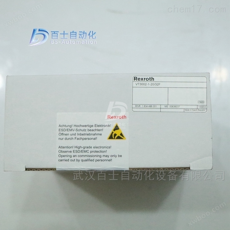
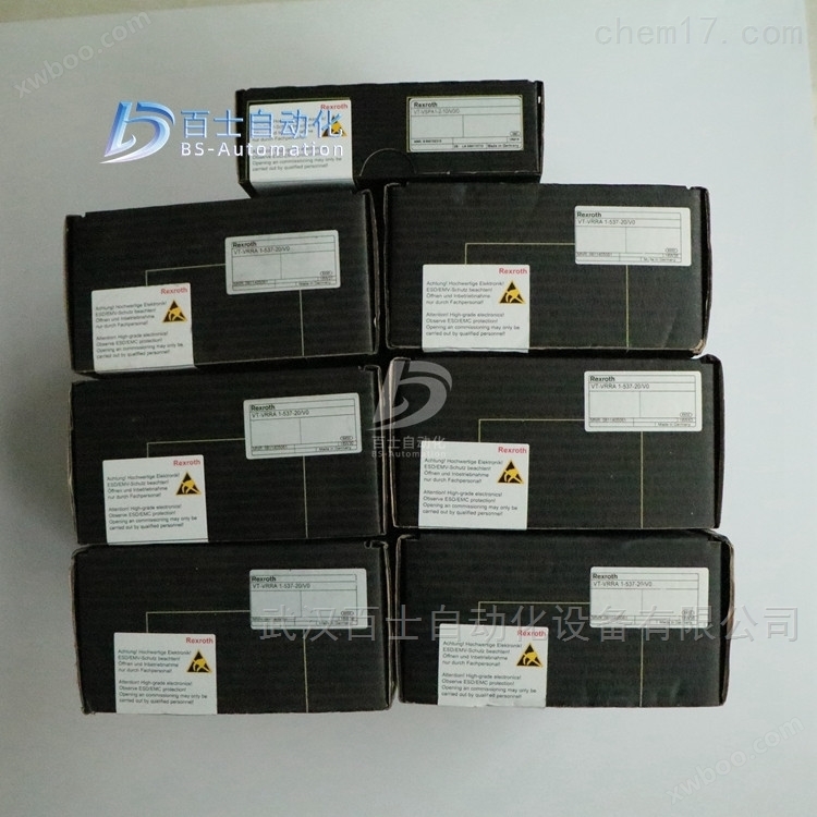
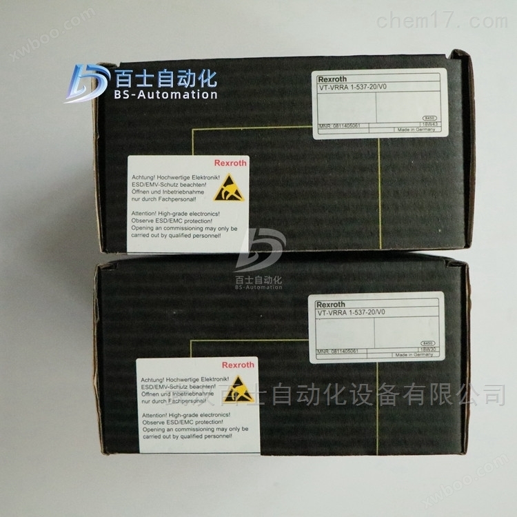
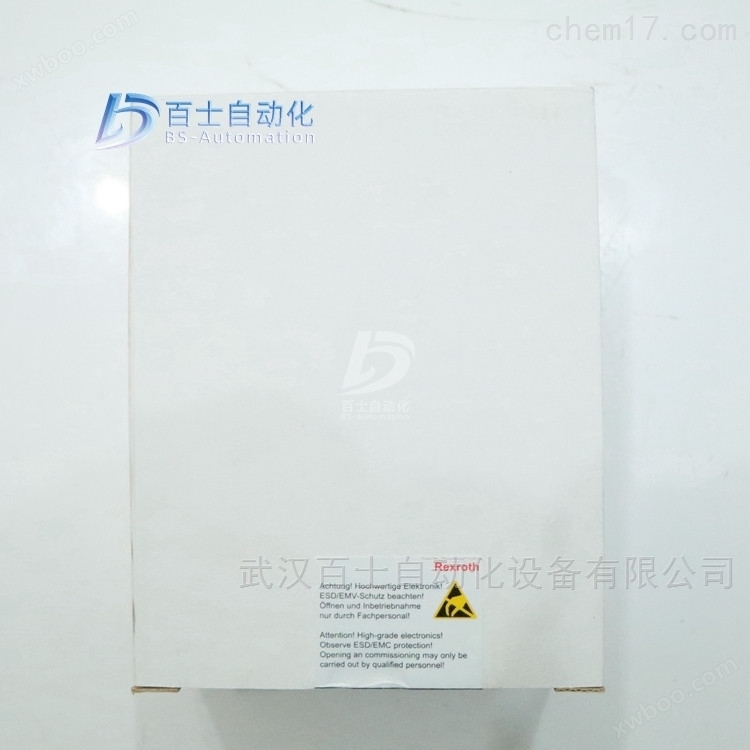
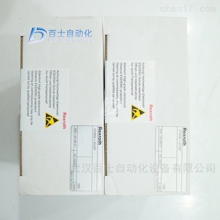
Rexroth enlarged version bracket VT3002-1-2X/48F
NegotiableUpdate on 01/22
- Model
- Nature of the Manufacturer
- Producers
- Product Category
- Place of Origin
Overview
Rexroth amplifier bracket VT3002-1-2X/48F, German REXROTH amplifier bracket, RexrOTH amplifier bracket, REXROTH amplifier installation bracket, RexrOTH amplifier connection terminal
Product Details
Rexroth enlarged version bracket VT3002-1-2X/48FGerman REXROTH amplifier bracket, Rexroth amplifier bracket, REXROTH amplifier installation bracket, Rexroth amplifier connection terminal, Wuhan Baishi Automation Equipment Co., Ltd. specializes in selling products that are original from the factory and refuse high imitation and counterfeit goods. Customers can buy and use with peace of mind. *Common products available in stock, welcome new and old customers to inquire and purchase!


Power amplifier:
Gradually increasing the input signal causes the valve core to start moving, but due to the excessive coverage of the valve port, there is no flow output at the valve outlet. Only when the valve port opening is about 25% of the large opening, there is flow output at the valve outlet.
When the input signal reaches or exceeds 25% of the large input signal, the valve outlet has a flow output, which depends on the opening of the valve.
When there is no control signal, excessive valve port coverage can reduce leakage, but from a control perspective, it is not desirable to have too much dead zone.
dead zone compensation
However, by adjusting the dead zone compensation potentiometer on the power amplifier, the dead zone can be reduced.
Firstly, set 1% (0.1V) of the input signal as the dead zone and maintain it.
However, when the input signal exceeds this threshold, the power amplifier output will skip the threshold to move the spool to the edge of the dead zone. At this point, a flow rate corresponding to the input signal of 0.1-0.2 V will be generated, and then the valve port will gradually open as the input signal increases. However, when the input signal is about 7.5V, the valve opening will be large. In fact, from the start to the end of the valve core movement, the dead zone is also moving.
Gain adjustment
By adjusting the gain potentiometer to reduce the gain of the power amplifier, this situation can be corrected. A decrease in gain means that a higher input signal is required to produce a certain output. The gain can be set in such a way that when the input signal reaches a large value, the valve opening should also be large.
If the dead zone compensation is set too low, there will be a large dead zone interval when the valve core starts to move.
However, if the dead zone compensation is set too high, when the input signal reaches the national value of 0.1V-0.2V, the spool movement will cross the dead zone, indicating that the proportional valve is difficult to control small flow.
If the gain is set too low, the proportional valve opening may not be large when the input signal is large (note: in some cases, to limit the large flow of the proportional valve, the gain can be set lower)
If the gain setting is too high, the proportional valve opening will have already reached a large value before the input signal reaches a large value.
The third adjustment function is used to determine the speed of change in the output of the power amplifier when the input signal changes. This is also known as slope adjustment. When the slope function is not selected, turn off or guide
The input signal will generate a sudden change in the input signal or corresponding output signal. If the inertial load in the system suddenly starts and stops, it will cause system oscillation. However, when selecting the ramp function, the output of the power amplifier is Constant speed variation (increase and decrease).
Generally speaking, in order to achieve a large opening of the proportional valve, the large ramp time can be set to 5 seconds.
Monitoring points on the front panel of the power amplifierSimplified the setting process. A monitoring point is used to indicate the input signal to the power amplifier, which is constrained by dead zone, gain, and ramp adjustments. The second monitoring point is used to indicate the displacement of the valve core (with feedback ratio)
Valve or feedback free proportional valve is used to indicate the output current (converted to constant voltage).
Hydraulic proportional control system
Proportional control components are used to complete power and motion direction control, which can be divided into proportional pressure valves, proportional flow valves, proportional directional valves, and proportional directional flow valves. They can be analog or digital inputs, and can be divided into open-loop control and closed-loop control depending on whether feedback is provided. Generally, the frequency obtained is not very high (10Hz), and high-frequency response valves can achieve higher frequencies.
If the accuracy requirement is not high, consider using an electro-hydraulic proportional control system. Generally, an electro-hydraulic proportional control system can achieve the following accuracy
Position accuracy -3 mm
Speed accuracy with pressure compensator -3%
Acceleration and deceleration ramp time -0.5 seconds
Product with pressure displacement sensor - proportional pressure valve set at 0.3% (if the pressure is set at 200 bar, the accuracy can reach 0.6 bar)
General multi drive hydraulic systems require flow and pressure control, providing proportional pressure and flow control systems
Open loop proportional pressure and flow control can be used for quantitative and variable pump systems.
The speed and flow ratio controls are:
Flow control only controls the fuel supply and does not control the direction of movement of the driving components;
If the system load and speed requirements are high, a speed control system should be used.
Speed proportional control is commonly used in automation control, injection molding machines, press machines, etc
The main reason for using a closed-loop system is:
Maintain the set value unaffected by external interference
Maintain a stable speed under different work pressures
Ensure the same position under different output forces
→ Synchronize movement under biased load
Improve accuracy requirements
Position error less than 1 mm
The pressure error is less than 1 ba
→ Need to control acceleration and deceleration
A system with high dynamic requirements
→ Simulation application
→ Test application
Rexroth enlarged version bracket VT3002-1-2X/48FGerman REXROTH amplifier bracket, Rexroth amplifier bracket, REXROTH amplifier installation bracket, Rexroth amplifier connection terminal
Rexroth Electrical Accessories
Rexroth REXROTH amplifier terminal block and socket
Rexroth REXROTH Connection Adapter
R900062692 VT10812-2X/32D
R900062584 VT10812-2X/48F
R900713826 VT10812-2X/64G
Rexroth REXROTH fully enclosed card plug-in box
R900784153 VT12302-3X/1
R978009974 VT12302-3X/2-64G DUAL CARD HOLD
Rexroth REXROTH 19 inch rack
R900016481 VT19101-1X/1EINFACHMAGAZIN160MM
R900016483 VT19101-1X/2EINFACHMAGAZIN220MM
R901222062 VT19101-1X/3EINFACHMAGAZIN220MM
R900016482 VT19102-1X/1DOPPELMAGAZIN160MM
R900016484 VT19102-1X/2DOPPELMAGAZIN220MM
R901178509 VT19103-1X/1DREIFACHMAGAZIN160MM
Rexroth installation card holder
R910908569 VT3002-2X/32RD29928
1834486002 VT3002-2-2X/32D
R900776300 VT3002-2X/32=CSA(KARTENHALTER)
R900209648 VT3002-1-2X/15H
R900020153 VT3002-1-2X/32D
R900020153 VT3002-1-20/32D
1834486001 VT3002-1-2X/32F
1834486001 VT3002-1-20/32F
R900020154 VT3002-1-2X/48F
R900020154 VT3002-1-20/48F
R900991843 VT3002-1-2X/64G
Rexroth REXROTH power supply and stabilization equipment
Rexroth REXROTH power module
R900010937 VT11006-1X/
R900010937 VT11006-12
Rexroth REXROTH capacitor module
R900020293 VT11110-1X/
Rexroth REXROTH power module
R900554828 VT11116-1X/ (MOD.VT11006-1X/+-10V)
Rexroth REXROTH integrated power supply unit
R900020164 VT-NE30-1X/
R987174925 VT-NE30-1X/
R901082348 VT-NE30-2X/
R900020165 VT-NE31-1X/
R900080049 VT-NE32-1X/
Basic principles of hydraulic transmission
In principle, the basic principle on which hydraulic transmission is based is Pascal's principle, which means that the pressure of the liquid is consistent throughout the system. Therefore, in a balanced system, the pressure applied to the smaller piston is relatively small, and the pressure applied to the larger piston is also relatively large, which can maintain the static state of the liquid. So through the transfer of liquid, different pressures can be obtained at different ends, thus achieving the purpose of transformation. The hydraulic jack we commonly see utilizes this principle to achieve force transmission. The components required in hydraulic transmission mainly include power components, actuating components, control components, auxiliary components, etc. The hydraulic power components are the parts that generate power for the hydraulic system, mainly including various hydraulic pumps. Hydraulic pumps work based on the principle of volume change, so they are generally also known as volumetric hydraulic pumps. Gear pump is a common hydraulic pump that moves liquid through the rotation of two meshing gears. Other hydraulic pumps include vane pumps and plunger pumps. When choosing a hydraulic pump, the main considerations include energy consumption, efficiency, and noise reduction. Hydraulic actuators are devices used to convert hydraulic energy provided by hydraulic pumps into mechanical energy, mainly including hydraulic cylinders and hydraulic motors. A hydraulic motor is a device that works in the opposite direction to a hydraulic pump, converting hydraulic energy into mechanical energy to perform external work. Hydraulic control components are used to control the direction of liquid flow, the level of pressure, and the expected control of flow rate to meet specific working requirements. It is precisely because of the flexibility of hydraulic control components that hydraulic control systems can accomplish different activities. Hydraulic control components can be divided into pressure control valves, flow control valves, and directional control valves according to their applications. According to the operation method, it can be divided into manual control valves, mechanical control valves, electric control valves, etc. In addition to the aforementioned components, hydraulic control systems also require hydraulic auxiliary components. These components include pipelines and pipe joints, fuel tanks, and filters Accumulator and sealing device. By using the above components, we can construct a hydraulic circuit. The so-called hydraulic circuit refers to the corresponding control circuit composed of various hydraulic components. According to different control objectives, we can design different circuits, such as pressure control circuit, speed control circuit, multi cylinder work control circuit, etc. According to the structure and characteristics of hydraulic transmission, in the design of hydraulic systems, the first step is to conduct system analysis, and then draft the schematic diagram of the system, which is represented by hydraulic mechanical symbols.
Afterwards, hydraulic components are selected through calculation, and then the system design and debugging are completed. The drawing of the schematic is crucial in this process. It determines the quality of a design system. The applicability of hydraulic transmission is very strong, such as the hydraulic system of loading and unloading stackers. As a storage machinery, it is used in modern warehouses to achieve mechanized loading and unloading of textile packages, oil drums, wooden barrels and other goods. It can also be applied in production practices such as hydraulic systems for cylindrical grinders. The characteristics of these systems are relatively high power, high production efficiency, and good stability.

Requirements for hydraulic oil performance
In hydraulic transmission, hydraulic oil is both a medium for transmitting power and a lubricant. It also plays a sealing role in some components, and the heat in the system is diffused through the oil, thus playing a role in heat dissipation. Therefore, in order to ensure the reliable, effective, and economical operation of hydraulic systems, hydraulic oil must meet the following requirements: 1) appropriate viscosity. Viscosity refers to the magnitude of intermolecular frictional resistance when an oil flows. When the viscosity is too high, the resistance of the oil flow is high, the energy loss is large, and the system efficiency is reduced. In addition, the no-load loss of the main engine increases, the temperature rises quickly, and the working temperature is high, which makes it easy for "cavitation" to occur at the suction end of the main pump. If the viscosity is too low, it cannot guarantee good lubrication conditions for hydraulic components, aggravate component wear, increase leakage, and reduce hydraulic system efficiency. 2) Good adhesion temperature characteristics. The viscosity temperature characteristic refers to the degree to which the viscosity of an oil changes with temperature, usually expressed as a viscosity index. The higher the viscosity index, the smaller the decrease in oil viscosity with increasing temperature during hydraulic system operation, thereby preventing excessive internal leakage in the hydraulic system. The viscosity index should generally not be lower than 90. 3) Good wear resistance and lubricity. The purpose is to reduce mechanical friction and ensure sufficient oil film strength under different conditions such as pressure, speed, and temperature. 4) High chemical reaction stability, not easily oxidized and deteriorated. Practice has proven that for every 10 ℃ increase in oil temperature, the chemical reaction rate doubles. Hydraulic oil with good antioxidant stability is less prone to oxidation and deterioration after long-term use, which can ensure the normal circulation of hydraulic oil. 5) The quality should be pure, and the content of mechanical impurities, moisture, and dust should be minimized as much as possible. 6) The impact on the sealing components should be minimal. 7) Good demulsibility, not easy to cause foam. Emulsification resistance refers to the ability of oil mixed with water and stirred to prevent it from becoming an emulsion, and to separate water from it. Foam resistance refers to the ability of mixing air into the oil and stirring it without forming emulsion and separating bubbles from the oil. Mixing water or air reduces the volume modulus of hydraulic oil, increases compressibility, slows down the action of hydraulic components, and is prone to impact and vibration. 8) Good rust prevention performance. Hydraulic oil covers the surface of the parts to prevent oxidation and corrosion. 9) Good shear stability. To improve the viscosity index of oil, high molecular weight polymers such as polymethyl methacrylate and polyisobutene are often added to the oil. These substances have long molecular chains, and when the oil flows through the narrow slits of hydraulic components, it is subjected to significant shear forces, often causing molecular chain breakage and a decrease in the viscosity temperature characteristics of the oil. 10) The ignition point and flash point should meet the ambient temperature and have low volatility to ensure the safe use of hydraulic oil.
Similar Product Recommend