-
E-mail
980227448@qq.com
-
Phone
15307180902
-
Address
Room 2003, 20th Floor, Building A, Luojiashan Building, No.7 Luojiashan Road, Hongshan District, Wuhan City
Product Categories
Wuhan Baishi Automation Equipment Co., Ltd
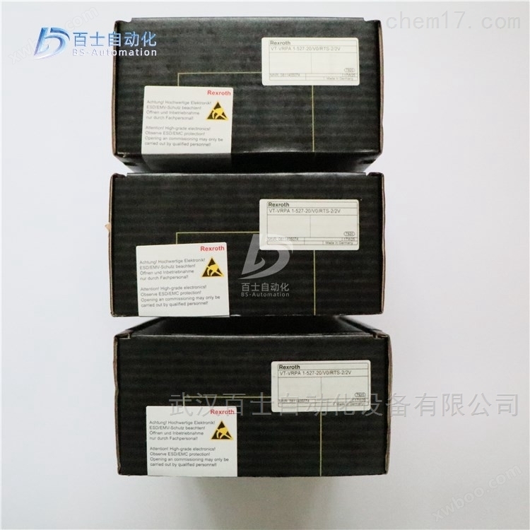
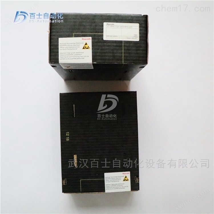
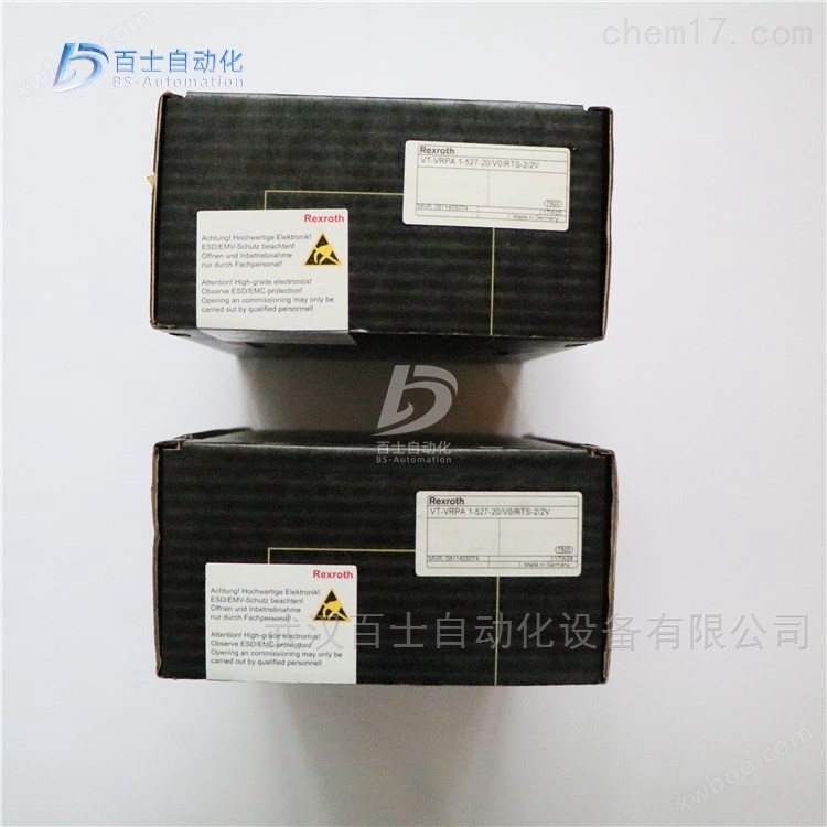
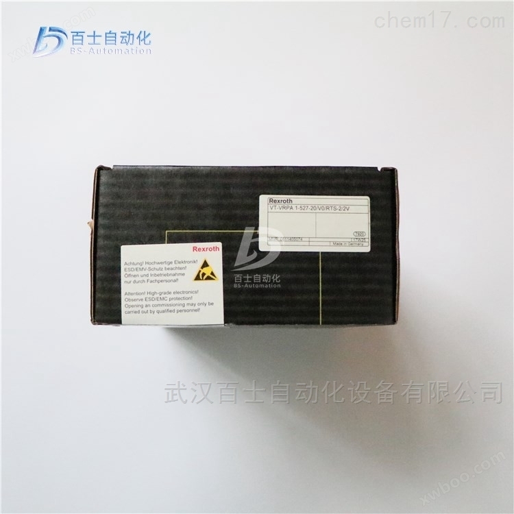
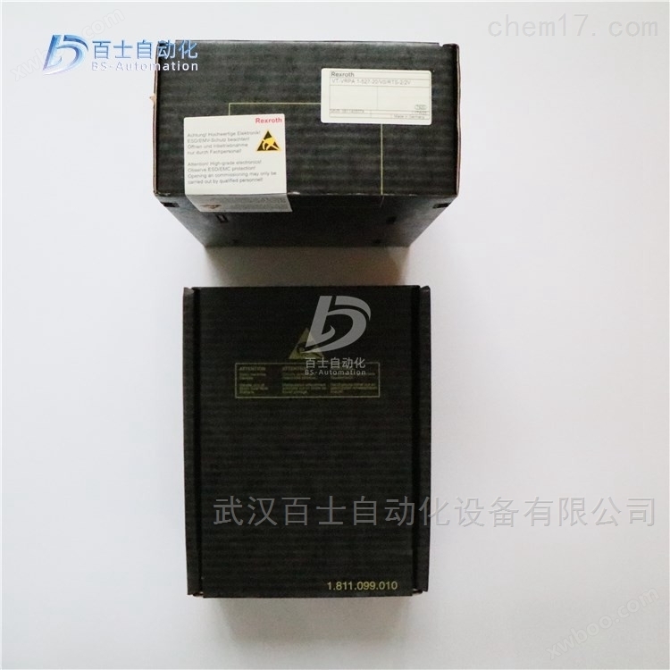
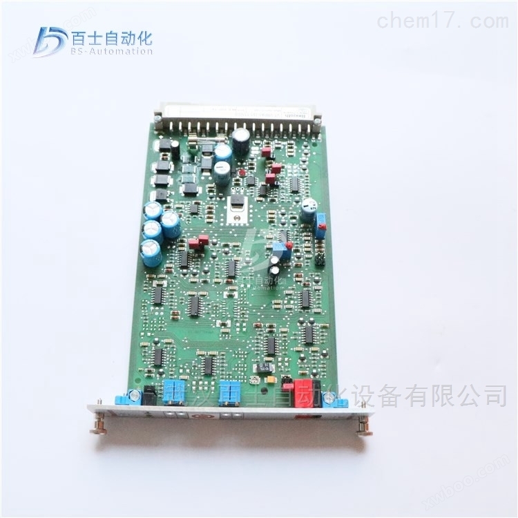
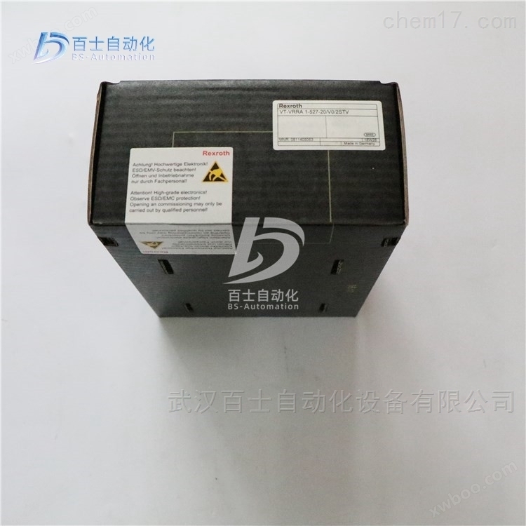
Rexroth enlarged version VT-VRPA1-527-20/V0/RTS-2/2V
NegotiableUpdate on 01/22
- Model
- Nature of the Manufacturer
- Producers
- Product Category
- Place of Origin
Overview
Rexroth enlarged version VT-VRPA1-527-20/V0/RTS-2/2V 0811405074, REXROTH enlarged version, German Rexroth analog circuit enlarged version, REXROTH proportional valve enlarged version
Product Details
Rexroth enlarged version VT-VRPA1-527-20/V0/RTS-2/2V0811405074, REXROTH amplification version, German Rexroth analog circuit amplification version, REXROTH proportional valve amplification version, Wuhan Baishi Automation Equipment Co., Ltd. specializes in selling products that are original from the factory and refuse high imitation counterfeit goods. Customers can buy and use with peace of mind. *Common products available in stock, welcome new and old customers to inquire and purchase!


Hydraulic amplifier refers to a power amplification device that uses pressure oil as the transmission medium and adjusts the low-power control signal at the input end to control the high-power hydraulic power at the output end.
Three port components: input, energy, output
Enlarged features:
Control high-power hydraulic power output with low-power input signals
The power at the output end comes from the energy source, and the magnitude of the hydraulic power at the output end is controlled by the input signal
The efficiency of an amplifier is equal to the ratio of the output power of the amplifier to the power delivered to the amplifier by the energy source.
Category: Throttle type hydraulic amplifier components (valve controlled)
Volumetric hydraulic amplification component (displacement control type)
Valve controlled: slide valve type, nozzle baffle type, jet tube type
Volumetric: Variable displacement pump, variable displacement motor
Hydraulic control valve, in valve controlled amplifier, directly controls the force and speed of the actuator; In volumetric amplification components, it directly controls the variable mechanism and indirectly controls the force and speed of the actuator by controlling the displacement.
Hydraulic control valve is a basic and important hydraulic amplifier.
The electro-hydraulic proportional valve is the main power amplifier component in the proportional control system, which continuously and proportionally controls the hydraulic system's pressure flow rate and other parameters according to the input electrical signal instructions. Compared with the servo valve in the servo control system, there is still a certain performance gap in some aspects (the main performance comparison is shown in Table 1), but its significant advantage is its strong anti pollution ability, which greatly reduces the work failures caused by pollution and improves the working stability and reliability of the hydraulic system. On the other hand, proportional valves have lower costs and simpler structures than servo valves, and have been widely used in many situations.
Proportional valves are divided into three categories based on their functions
(1) Proportional pressure valve. There are overflow valves and pressure reducing valves, which have two structures: direct acting and pilot operated; It can remotely control its output oil pressure continuously or proportionally;
(2) Proportional directional valve. There are two types of structures: direct acting and pilot operated. Direct acting valves have two types: those with displacement sensors and those without displacement sensors. Due to the use of proportional solenoid valve cores, not only can they be rotated, but the stroke of rotation can also be continuously or proportionally changed. Therefore, the flow area between the connected oil ports can also vary continuously or proportionally. So the proportional directional valve can not only control the direction of the actuator but also its speed. For this reason, proportional directional valves in proportional valves are also commonly used;
(3) Proportional flow valve. There are proportional speed control valves and proportional overflow flow control valves, which can remotely control their output flow continuously or proportionally.
The input unit of a proportional valve is an electro-mechanical converter, which converts the input electrical signal into mechanical quantity converters in the form of servo motors, stepper motors, force motors, torque motors, proportional electromagnets, etc. However, most commonly used proportional valves use proportional electromagnets, which are designed based on electromagnetic principles to generate mechanical quantities (force or torque and displacement) proportional to the input electrical signal (current), and continuously control the position of the hydraulic valve core, thereby achieving continuous control of the pressure direction and flow rate of the hydraulic system. The structure of a proportional electromagnet consists of a coil, an armature push rod, etc. When a signal is input to the coil, the magnetic field inside the coil exerts a force on the armature. The armature moves continuously in proportion to the magnitude and direction of the signal current in the magnetic field, and then drives the push rod through a fixed pin to control the movement of the slide valve core. The proportional electromagnet used is a high-voltage DC resistant proportional electromagnet.
The types of proportional electromagnets are mainly classified according to their working principles
The following categories:
(1) Force controlled type
This type of electromagnet has a short stroke of only 1.5mm, and the output force is proportional to the input current. It is commonly used in the pilot control stage of proportional valves
Above:
(2) Travel control type
Composed of force controlled and loaded springs, the force output by the electromagnet is converted into output displacement through the spring. The output displacement is proportional to the input current, with a working stroke of 3mm and good linearity. It can be used in direct control proportional valves;
(3) Position adjustment type
After the position of the armature is detected by the sensor, a feedback signal is sent out inside the valve, and the position of the armature is readjusted after comparison inside the valve. Closed loop control is formed inside the valve, with high precision and the position and force of the armature
It's irrelevant, high-precision proportional valves such as Bosch from Germany and Atos from Italy all use this structure.
The proportional valve is used in conjunction with an amplifier. The amplifier adopts current negative feedback, and is equipped with a ramp signal generator, step function generator, PD regulator, inverter, etc., to control the boost and buck time or motion acceleration and deceleration. When the power is cut off, it can keep the valve core in a safe position.
The proportional solenoid and hydraulic valve form an electro-hydraulic proportional valve. Due to the fact that proportional electromagnets can obtain different forces (or strokes) at different currents, they can infinitely change pressure and flow rate. Therefore, the proportional electromagnet is a key component of the proportional valve.
Rexroth enlarged version VT-VRPA1-527-20/V0/RTS-2/2V0811405074, REXROTH enlarged version, German Rexroth analog circuit enlarged version, REXROTH proportional valve enlarged version
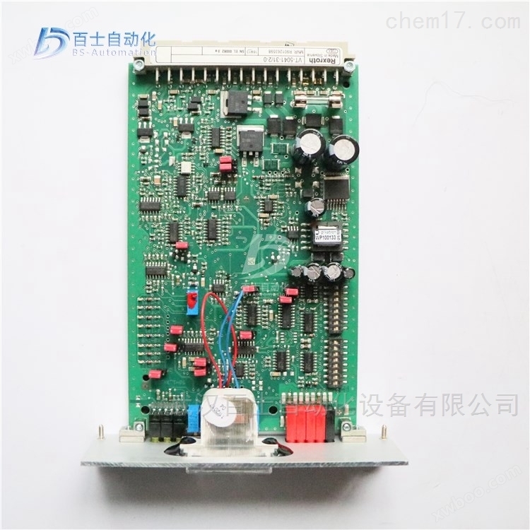
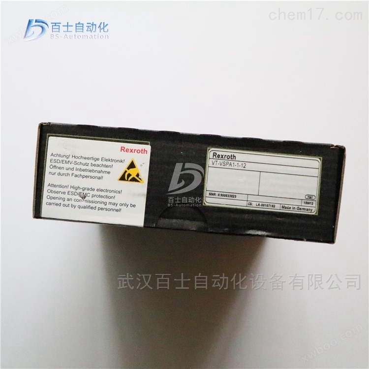
Rexroth REXROTH valve amplifier with electric position feedback proportional valve
Rexroth REXROTH Analog Amplification Module
R900752430 VT-MRMA1-1-1X/V0/0
R900779644 VT-MRPA1-100-1X/V0/0
R901080965 VT-MRPA1-150-1X/V0/0
R901080966 VT-MRPA1-151-1X/V0/0
R901416700 VT-MRPA1-151-1X=V0/0
R901094750 VT-MRPA1-1-1X/V0/0
R901094751 VT-MRPA1-2-1X/V0/0
R900249895 VT-MRPA2-1-1X/V0/0
R900249811 VT-MRPA2-2-1X/V0/0
Rexroth REXROTH analog circuit amplification version, European version standard
0811405095 VT-VRPA1-527-10/V0
0811405096 VT-VRPA1-527-10/V0/PV
0811405098 VT-VRPA1-527-10/V0/QV
0811405097 VT-VRPA1-537-10/V0/PV
0811405099 VT-VRPA1-537-10/V0/QV
0811405101 VT-VRPA1-527-10/V0/PV-RTP
0811405103 VT-VRPA1-527-10/V0/QV-RTP
0811405100 VT-VRPA1-527-10/V0/RTP
0811405102 VT-VRPA1-537-10/V0/PV-RTP
0811405104 VT-VRPA1-537-10/V0/QV-RTP
081145074 vt -vrppa1-527-20 / V0 / RTs -2 / 2V
R978022097 VT-VRPA1-100-1X/SO43A-466B
R901009038 VT-VRPA1-100-1X/V0/0
R901057058 VT-VRPA1-150-1X/V0/0
R901057060 VT-VRPA1-151-1X/V0/0
R901057060 VT-VRPA1-151-11/V0/0
R901057060 VT-VRPA1-151-12/V0/0
R900952202 VT-VRPA1-50-1X/
R900619297 VT-VRPA1-50-1X/001 FEDERLEIST 32POLIG F
R978911504 VT-VRPA1-50-1X/SO43A-472B
R900952204 VT-VRPA1-51-1X/
R979810986 VT-VRPA1-51-1X/ SO41-7519
R978031853 VT-VRPA1-51-1X/SO43A-1828
R900952205 VT-VRPA1-52-1X/
R900979887 VT-VRPA2-1-1X/V0/T1
R900979887 VT-VRPA2-1-11/V0/T1
R900979885 VT-VRPA2-1-1X/V0/T5
R900979889 VT-VRPA2-2-1X/V0/T1
R900979888 VT-VRPA2-2-1X/V0/T5
R900067617 VT-VRM1-1-1X/
Forging machinery refers to the mechanical equipment used for forming and separating in forging processing. Forging machinery includes forging hammers, mechanical presses, hydraulic presses, screw presses, and flat forging machines used for forming, as well as auxiliary machinery such as unwinding machines, straightening machines, shearing machines, and forging operation machines. Forging machinery is mainly used for metal forming, so it is also known as metal forming machine tool. Forging machinery is formed by applying pressure to metal, with high force being its basic characteristic. Therefore, it is mostly heavy-duty equipment, and safety protection devices are often installed on the equipment to ensure the safety of both the equipment and personnel.
Forging machinery mainly includes various forging hammers, various press machines, and other auxiliary machinery.
Forging hammer is a mechanical device that uses the kinetic energy generated by the falling or forced high-speed motion of a heavy hammer to perform work on a billet, causing it to undergo plastic deformation. Forging hammer is a common and long-standing forging machinery. It has a simple structure, flexible operation, strong functionality, wide application, and easy maintenance, suitable for free forging and die forging. But the vibration is significant, making it difficult to achieve automated production.
Working principle of forging hammer
The forging hammer relies on the sudden release of energy from high-pressure gas to drive the upper and lower hammer heads to move at high speed and strike in suspension, which is a forging method for metal plastic forming. High speed hammer forging is a high-energy forming method mainly used for precision forging and hot extrusion.
The high-pressure gas released instantly (usually at a pressure of 15000 megapascals) forces the hammer head to move downwards at a high speed of 9-24 meters per second, while also pushing up the cylinder head of the high-pressure cylinder and driving the entire frame to move upwards. The upper mold on the hammer head and the lower mold on the frame collide with the workpiece in the air, causing plastic deformation. The mass of the frame is much larger than that of the hammer body, so the movement speed is slow, the stroke is small, and it is easy to operate. After hammering, the return rod installed in the frame pushes the hammer head back to its original position. The frame is placed on the buffer pad of the outer bracket. This type of equipment can only be clicked once, but later developed into a high-speed hammer that can be linked and internal combustion type. High speed hammer forging has significant deformation inertia force and deformation thermal effect. Proper control can improve the plasticity of the metal, enhance the flow and filling performance of the metal in the mold, and use forging to form complex shaped forgings with thin walls and high ribs. High speed hammer forging is commonly used for precision forging and extrusion of parts such as blades and gears.
Mechanical press, which is driven by crank connecting rod or elbow mechanism, cam mechanism, and screw mechanism, works smoothly, has high precision, good operating conditions, high productivity, and is easy to achieve mechanization and automation. It is suitable for working on automatic lines. Mechanical presses rank among all types of forging machinery in terms of quantity. Various wire forming automatic machines such as cold heading machines, flat forging machines, screw presses, radial forging machines, most bending machines, straightening machines, and shearing machines also have transmission mechanisms similar to mechanical presses, which can be said to be a derivative series of mechanical presses.
Working principle of mechanical press
It is driven by crank connecting rod or elbow mechanism, cam mechanism, screw mechanism, with smooth operation, high precision, good operating conditions, high productivity, easy to achieve mechanization and automation, suitable for working on automatic lines. Mechanical presses rank among all types of forging machinery in terms of quantity. Various wire forming automatic machines such as cold heading machines, flat forging machines, screw presses, radial forging machines, most bending machines, straightening machines, and shearing machines also have transmission mechanisms similar to mechanical presses, which can be said to be a derivative series of mechanical presses. The itinerary is variable and can generate significant working force at any position. The hydraulic press works smoothly without vibration, and is easy to achieve a large forging depth. It is suitable for forging large forgings and deep drawing, packaging, and pressing of large-sized sheet metal. Hydraulic presses mainly include hydraulic presses and hydraulic presses. Some bending, straightening, and shearing machines also belong to the category of hydraulic presses.

Hydraulic system structure
The hydraulic system consists of two parts: signal control and hydraulic power. The signal control part is used to drive the control valve action in the hydraulic power part.
The hydraulic power part is represented by a circuit diagram to indicate the interrelationships between different functional components. The hydraulic source contains a hydraulic pump, an electric motor, and hydraulic auxiliary components; The hydraulic control part contains various control valves, which are used to control the flow rate, pressure, and direction of the working oil; The execution part contains hydraulic cylinders or hydraulic motors, which can be selected according to actual requirements.
slipway for Combined Machine Tools
The power slide table is a universal component of the combination machine tool, on which cutting heads for various process purposes can be configured. The hydraulic power slide table of machine tools can achieve various working cycles, among which a typical working cycle is: fast forward → first working forward → second working forward → dead stop iron stop → fast retreat → stop. Differential connection of hydraulic cylinders to achieve rapid movement; The system adopts a pressure limiting variable vane pump for oil supply; Use stroke valves and hydraulic control sequence valves to switch between fast forward and working in; The electro-hydraulic directional valve enables differential connection between the hydraulic cylinder and the variable displacement pump to achieve rapid movement;
(1) Fast forward and press the start button. The pilot solenoid directional valve 1YA of the three position five way electro-hydraulic directional valve 5 is powered on, causing the valve core to move to the right and enter the working state in the left position. Use a two position two-way electromagnetic directional valve to achieve speed switching between the first and second working inputs.
(2) At the end of the fast forward stroke, the stop iron on the slide table presses the travel valve. Use stroke valves and hydraulic control sequence valves to switch between fast forward and working in; Use a two position two-way electromagnetic directional valve to achieve speed switching between the first and second working inputs.
(3) In order to ensure the dimensional accuracy of the second feed, a dead stop iron was used to limit the position.
(4) When the dead stop iron is stopped at the end of the second working feed of the power slide table, the hydraulic cylinder stops moving and the system pressure further increases. When it reaches the set value of pressure relay 15, after a delay of the time relay, an electrical signal is sent out again to retract the slide table. Before the delay action of the time relay, the sliding table stays at the position limited by the dead stop block.
(5) After the fast return time relay sends an electrical signal, the electro-hydraulic reversing valve works in the right position. At this point, the system pressure is low, and the output flow of variable pump 2 is high, causing the power slide table to quickly retract. Due to the fact that the area of the piston rod is approximately half that of the piston, the forward and backward speeds of the power slide are roughly equal.
(6) When the power slide returns to its original position, the stop block presses the travel switch, the electro-hydraulic directional valve is in the neutral position, the power slide stops moving, and the variable pump unloads.
Similar Product Recommend