-
E-mail
980227448@qq.com
-
Phone
15307180902
-
Address
Room 2003, 20th Floor, Building A, Luojiashan Building, No.7 Luojiashan Road, Hongshan District, Wuhan City
Product Categories
Wuhan Baishi Automation Equipment Co., Ltd
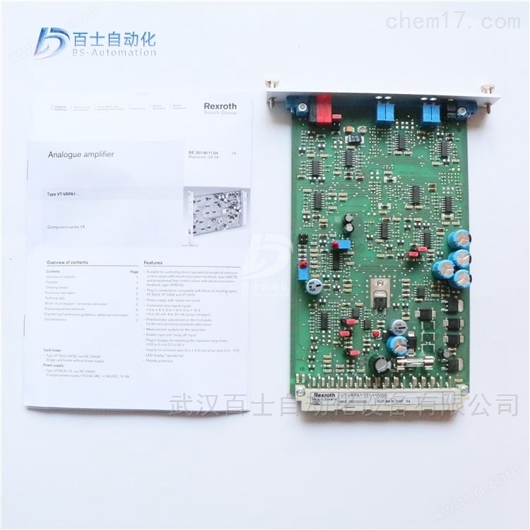
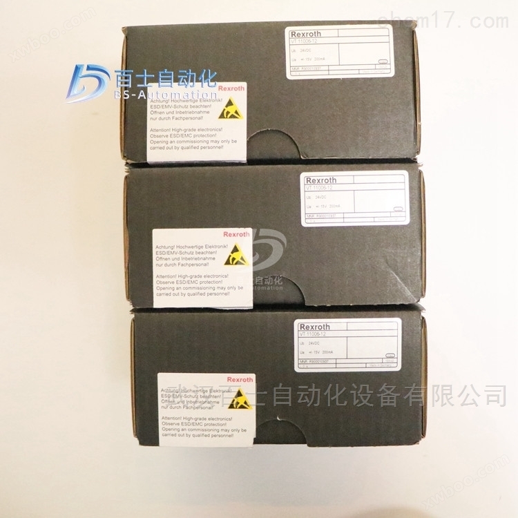
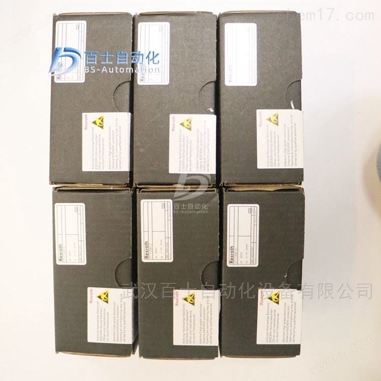
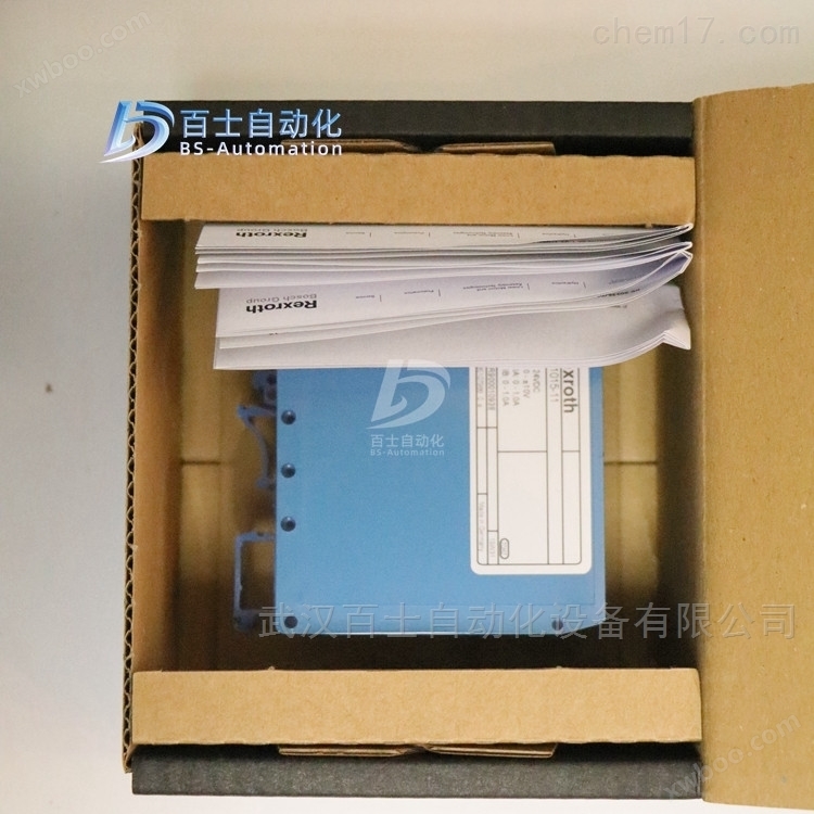
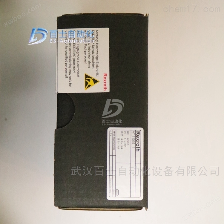
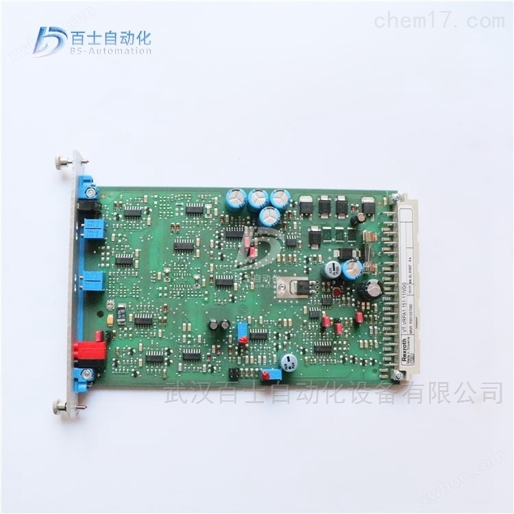
REXROTH enlarged version VT-VRPA2-1-1X/V0/T5
NegotiableUpdate on 01/22
- Model
- Nature of the Manufacturer
- Producers
- Product Category
- Place of Origin
Overview
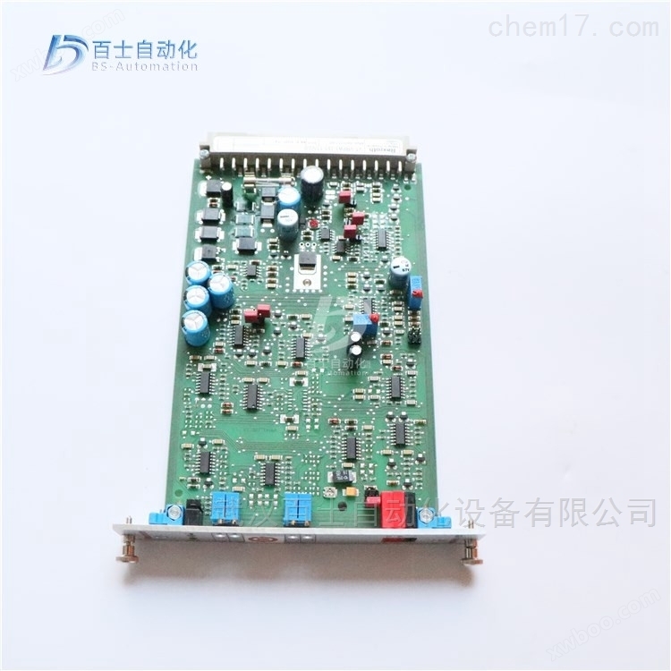
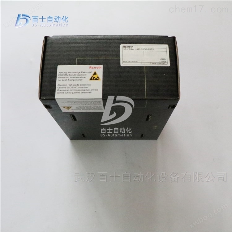
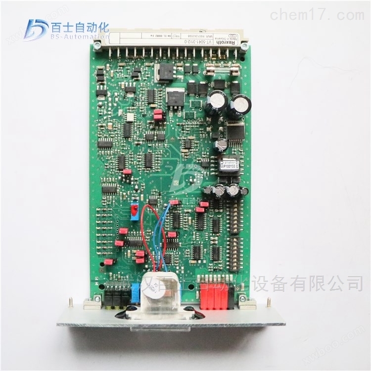
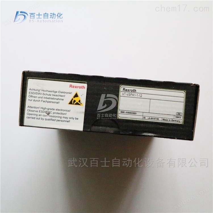
REXROTH amplification version VT-VRPA2-1-1X/V0/T5, Rexroth amplification version, REXROTH proportional valve amplification version, Rexroth analog circuit amplification version, REXROTH amplifier, Rexroth proportional valve amplifier
Product Details
REXROTH 放大版 VT-VRPA2-1-1X/V0/T5Rexroth amplification version, REXROTH proportional valve amplification version, Rexroth analog circuit amplification version, REXROTH amplifier, Rexroth proportional valve amplifier, Wuhan Baishi Automation Equipment Co., Ltd. specializes in selling products that are original from the factory and refuse high imitation and counterfeit goods. Customers can buy and use with peace of mind. *Common products available in stock, welcome new and old customers to inquire and purchase!

proportional control valve
A valve that uses a proportional electromagnet (or torque motor) to convert input signals into force or mechanical displacement of the valve, so that the output (pressure, flow) of the valve is continuously and proportionally controlled according to its input quantity.
There are several types of proportional valves used on site in large steel mills, including servo proportional control valves, proportional control valves, electro-hydraulic proportional control valves, proportional valves, and servo valves.
1. 4WRD E. proportional servo control valve (high-frequency response valve)
Structure and Function
The 4WRDE type valve is a three-stage high-frequency directional valve. This valve can be used for open-loop control or closed-loop regulation of the size and direction of fluid flow, but is mainly used in closed-loop regulation circuits.
The valve is mainly composed of the following parts:
The secondary pilot control valve consists of a torque motor (1), a hydraulic amplifier (5) composed of a nozzle baffle valve, and a valve core liner assembly (6) used as a flow amplification stage (to control the third stage (7)).
The third level (7) is used for flow control.
3. Inductive displacement sensor (8), connected to the magnetic core (9) of the third stage main valve core (10)
Realize valve closed-loop control signal logic connection, position detection system feedback, and pilot valve control through built-in electronic amplifier.
The differential voltage obtained by comparing the given value with the actual value is amplified by an electronic controller and transmitted as a control deviation to the first stage of the valve. This signal drives the baffle (2) between the two control nozzles (3.1, 3.2), thus creating a pressure difference between the two control chambers (11.1.11.2). The control valve core (4) is therefore pushed and flows through the corresponding liquid flow to the spring chamber (12.1 or 12.2). The valve core (10) and the displacement sensor (8) with magnetic core (9) move straight until the actual value and the given value signal are equal again. Under controlled conditions; The main valve core (10) is always maintained at the position corresponding to the given value.
The spool stroke is proportional to the given value. By adjusting the position of the valve core (10) relative to the control edge (13), a corresponding valve opening proportional to the flow rate is formed.
The dynamic characteristics of the valve are optimized through an electronic amplifier. The electronic amplifier is built into the valve (oscillator, demodulator)
Zero point adjustment is pre-set by the manufacturer and can be adjusted within 10% of the nominal range through closed-loop control of the potentiometer inside the electronic amplifier. Remove the plug at the end of the valve cover to operate the built-in closed-loop electronic amplifier.
2. 4WREE proportional control valve
1. Structure and functional principles
The two position four-way and three position four-way proportional directional valves are directly controlled and have a plate structure; Operated by proportional electromagnetic, proportional electromagnetic With a central thread, the ring can be disassembled separately, and electromagnetic control can be achieved through an external amplifier (WRA type) or a built-in amplifier (WRAE type).
Structure:
This valve consists of the following parts:
Valve body with installation bottom (1)
Control valve core (2) with springs (3 and 4)
Electromagnets with central thread (5 and 6)
Displacement sensor (7)
Optional with built-in amplifier (8)
Mechanical zero adjustment (9),
Working principle:
When the electromagnets (5 and 6) are not charged, the centering springs (3 and 4) keep the control valve core (2) in the neutral position
After the proportional electromagnetic coil is energized, it will directly push the control valve core (2). For example, when the control electromagnetic coil 'b' (6) is excited, the control valve core (2) is pushed to the left, and the displacement is proportional to the input electrical signal. At this time, the P to A and B to T ports communicate with the valve body through the throttle formed by the valve core and the valve body, and have progressive flow characteristics. Electromagnetic coil (6) power loss control The valve core (2) is pushed back to the center position by the centering spring (3).
In the event of a loss of power to the electromagnet, the valve core (2) remains in the mechanical neutral position under the action of the electromagnetic reset spring. This is not related to the hydraulic center position for the valve core with the function symbol "V"! When the valve is closed for closed-loop control, the spool is placed in the hydraulic neutral position.
It is necessary to avoid completely draining the oil in the return line, and if necessary, install a back pressure valve (back pressure of about 2 bar) in the circuit.
3. 4WR... type proportional control valve
3. Structure and functional principles
Pilot control valve model 3DREP 6... This pilot valve is a three-way pressure reducing valve controlled by a proportional solenoid. Its function is to convert an input electrical signal into a pressure output signal proportional to it, which can be used for the control of all 4WRZ... and 5WR... proportional valves.
The proportional electromagnet is an adjustable, wet DC electromagnetic structure with a central thread, and the coil can be disassembled separately; Electromagnetic control can be achieved through external amplifiers (WRZ type) or built-in amplifiers (WRZE type).
Structure:
The valve mainly consists of the following parts:
(1) Shell with installation bottom surface (1);
(2) Control valve core (2) equipped with pressure measuring pistons (3 and 4);
(3) Electromagnetic coil with central thread (5 and 6);
(4) Optional with built-in amplifier (7)
Working principle:
(1) When the electromagnets (5 and 6) are not charged, the centering spring keeps the control valve core (2) in the neutral position;
(2) After the proportional electromagnet is energized, it will directly push the control valve core (2), for example: the electromagnetic "a" (5) is excited;
(3) The control valve core (2) and pressure measuring piston (3) are pushed to the left;
(4) Displacement is proportional to the input electrical signal.
At this point, the P and B ports, as well as the A and T ports, are connected through the throttle port 1 formed by the valve core and valve body, and the throttling characteristics are progressive. If the electromagnet (5) loses power, the control valve core (2) is pushed back to the neutral position by the spring. In the middle position of the pilot valve, ports A, B, and T are connected, which also means that the oil can be directly returned to the tank from here.
Pilot operated proportional directional valve, models 4WRZ. and 5WRZ., 4WRZ. valve is a pilot operated, proportional solenoid valve
A four-way directional valve that controls the direction and magnitude of fluid flow.
Structure:
The valve mainly consists of the following parts:
(1) Equipped with proportional electromagnetic Pilot control valve (9) for (5 and 6)
(2) Main valve (10) equipped with main valve core (11) and centering spring (12)
Working principle:
(1) When the electromagnets (5 and 6) are not charged, the centering spring (12) keeps the main valve core (11) in the neutral position.
(2) The action of the main valve core (11) is controlled by the pilot valve (9) - it is indirectly pushed proportionally by the electromagnet "b '(6). Firstly, the control valve core (2) is pushed to the right, and the control oil enters the control chamber (13) through the pilot valve (9), and pushes the main valve core (11) in proportion to the input signal. At this time, the P port, A port, B port, and T port are connected through the throttle port formed by the valve core and valve body, and the throttle characteristic is gradual.
(3) The control oil required for the pilot valve can be supplied through P port or X port.
(4) If the electromagnet (6) loses power, the control valve core (2) and the main valve core (11) will return to the neutral position.
(5) Depending on the position of the main valve core, P port is connected to A port, B port is connected to T port (R), or P port is connected to B port, A port is connected to T port (R). Optional protective cover for manual emergency operation (14 and 15), which allows the pilot valve core (2) to move in the absence of electromagnetic power.
REXROTH 放大版 VT-VRPA2-1-1X/V0/T5Rexroth amplification version, REXROTH proportional valve amplification version, Rexroth analog circuit amplification version, REXROTH amplifier, Rexroth proportional valve amplifier
Rexroth REXROTH analog circuit amplification version, European version standard
0811405095 VT-VRPA1-527-10/V0
0811405096 VT-VRPA1-527-10/V0/PV
0811405098 VT-VRPA1-527-10/V0/QV
0811405097 VT-VRPA1-537-10/V0/PV
0811405099 VT-VRPA1-537-10/V0/QV
0811405101 VT-VRPA1-527-10/V0/PV-RTP
0811405103 VT-VRPA1-527-10/V0/QV-RTP
0811405100 VT-VRPA1-527-10/V0/RTP
0811405102 VT-VRPA1-537-10/V0/PV-RTP
0811405104 VT-VRPA1-537-10/V0/QV-RTP
081145074 vt -vrppa1-527-20 / V0 / RTs -2 / 2V
R978022097 VT-VRPA1-100-1X/SO43A-466B
R901009038 VT-VRPA1-100-1X/V0/0
R901057058 VT-VRPA1-150-1X/V0/0
R901057060 VT-VRPA1-151-1X/V0/0
R901057060 VT-VRPA1-151-11/V0/0
R901057060 VT-VRPA1-151-12/V0/0
R900952202 VT-VRPA1-50-1X/
R900619297 VT-VRPA1-50-1X/001 FEDERLEIST 32POLIG F
R978911504 VT-VRPA1-50-1X/SO43A-472B
R900952204 VT-VRPA1-51-1X/
R979810986 VT-VRPA1-51-1X/ SO41-7519
R978031853 VT-VRPA1-51-1X/SO43A-1828
R900952205 VT-VRPA1-52-1X/
R900979887 VT-VRPA2-1-1X/V0/T1
R900979887 VT-VRPA2-1-11/V0/T1
R900979885 VT-VRPA2-1-1X/V0/T5
R900979889 VT-VRPA2-2-1X/V0/T1
R900979888 VT-VRPA2-2-1X/V0/T5
R900067617 VT-VRM1-1-1X/
Rexroth REXROTH digital enlarged version, European version standard
R901066987 VT-VRPD-2-2X/V0/0-0 * Three control blocks
This style has three control blocks. Two main control blocks with corresponding intermediate plate filling valves are directly installed on the hydraulic cylinder, achieving a pipeline free connection between the main control block and the hydraulic cylinder chamber. The main control block of the bending machine is mainly composed of important proportional directional valves, position monitoring directional valves, and back pressure components.
3. Interface distributor for sensors and shafts
*In the application of the control block in the bending machine, all solenoid valves are centralized in one control block, and similarly, the electrical connections of each valve are also centralized on one cable line, achieving a common connection. For this purpose, an interface distributor has also been installed on the control block of the bending machine.
Proportional valve is a new type of valve with certain characteristics of servo valve and switching valve. Compared with servo valves, proportional valves have the advantages of low energy loss, low requirements for oil filtration accuracy, and moderate price. Therefore, they have gradually been promoted and applied in domestic forging machinery.
The proportional valves mainly used in sheet metal bending machines are proportional overflow valves and proportional speed regulating valves. Proportional overflow valves generally control the bending pressure of sheet metal bending machines; The proportional speed control valve is mainly used to control the synchronization and depth of the slider of the sheet metal bending machine. The proportional valve is often combined with computer control technology in the application of sheet metal bending machines, becoming a CNC sheet metal bending machine synchronized with electro-hydraulic proportional control, namely hydraulic synchronous CNC sheet metal bending machine.

Load sensing and pressure compensation technology for electro-hydraulic proportional multi way valve
Saving energy, reducing oil temperature, and improving control accuracy, while also ensuring that the synchronous action of several executing components does not interfere with each other during movement, load sensing and pressure compensation technology are now widely used in construction machinery. Load sensing and pressure compensation are very similar concepts, both of which use pressure changes caused by load changes to regulate pump or valve pressure and flow to meet system operating requirements. For a quantitative pump system, load sensing refers to directing the load pressure load sensing oil circuit to a remote pressure regulating relief valve. When the load is small, the relief valve's set pressure is also small; The load is large and the set pressure is also high, but there is always a certain overflow loss. The variable pump system introduces the load sensing oil circuit into the pump variable mechanism, so that the pump output pressure increases with the increase of load pressure (always a small fixed pressure difference), making the pump output flow equal to the actual required flow of the system, without overflow loss, and achieving energy saving. Pressure compensation is a guarantee measure taken to improve valve control performance. The load pressure behind the valve port is introduced into the pressure compensation valve, which adjusts the pressure in front of the valve port to maintain a constant pressure difference. This way, the flow regulation characteristics of the throttle port are only related to the opening of the valve port, and are not affected by the load pressure.
Pilot control and remote control of electro-hydraulic proportional valve in construction machinery
The technological advancement of electro-hydraulic proportional valves and other components has made electrical control of various systems such as gear shifting, steering, braking, and working devices in construction vehicles a reality. Generally, the displacement output mechanism can be achieved by using a proportional servo control manual multi way valve driver. Electrical operation has the advantages of fast response, flexible wiring, integrated control, and easy interface with computers. Modern engineering machinery hydraulic valves have increasingly adopted electrically controlled pilot controlled electro-hydraulic proportional valves (or electro-hydraulic switching valves) instead of manual direct operation or hydraulic pilot controlled multi way valves. Another significant advantage of using electro-hydraulic proportional valves (or electro-hydraulic switching valves) is that the number of operating handles can be greatly reduced on construction vehicles, which simplifies the layout of the cab and effectively reduces operational complexity. This has important practical significance for improving work quality and efficiency.
Similar Product Recommend