-
E-mail
980227448@qq.com
-
Phone
15307180902
-
Address
Room 2003, 20th Floor, Building A, Luojiashan Building, No.7 Luojiashan Road, Hongshan District, Wuhan City
Product Categories
Wuhan Baishi Automation Equipment Co., Ltd
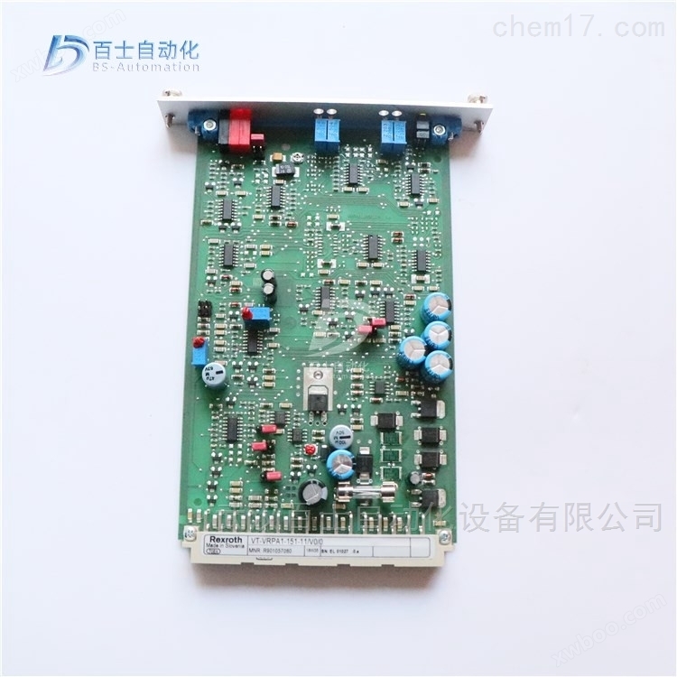
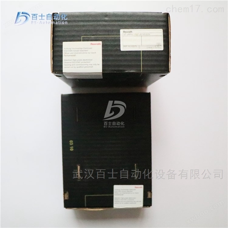
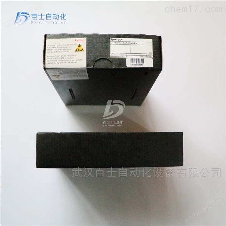
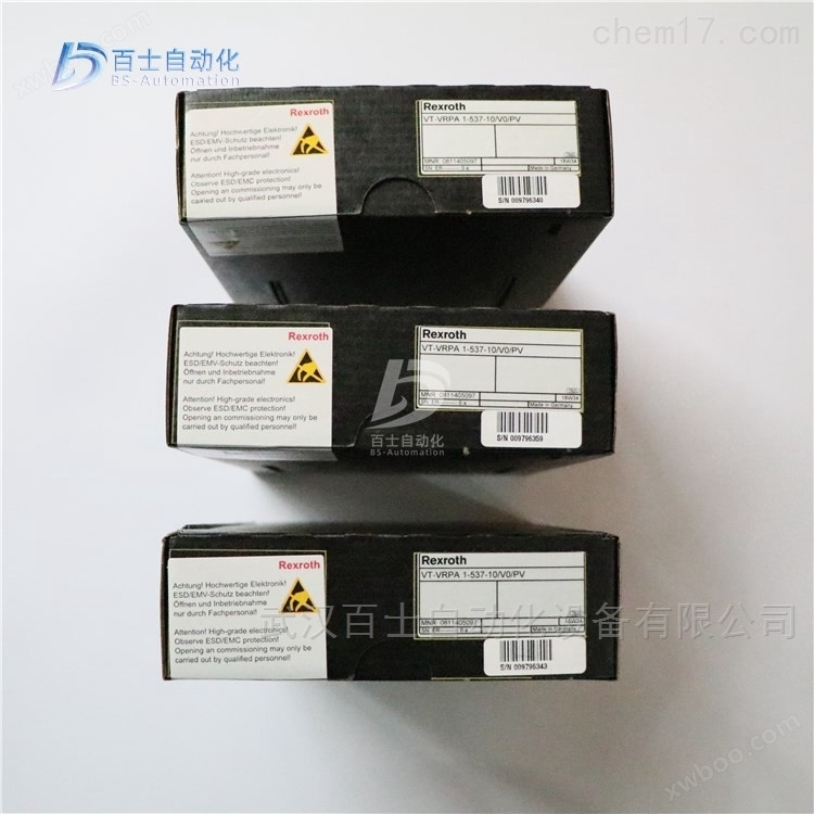
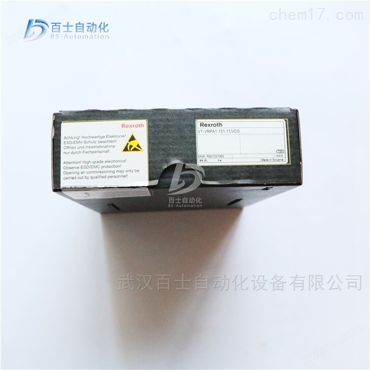
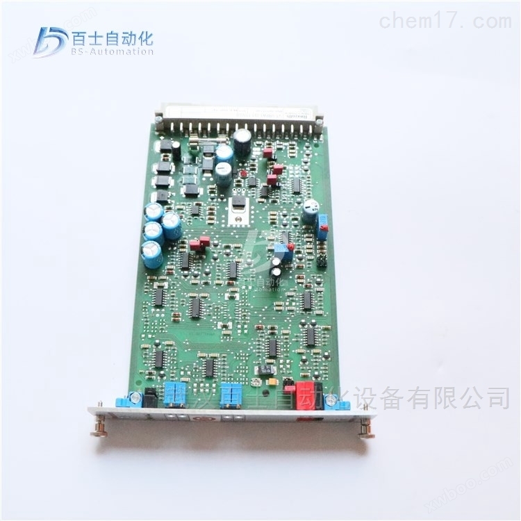
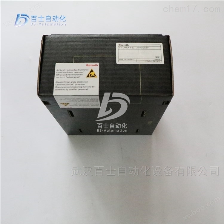
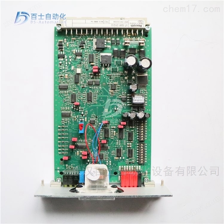
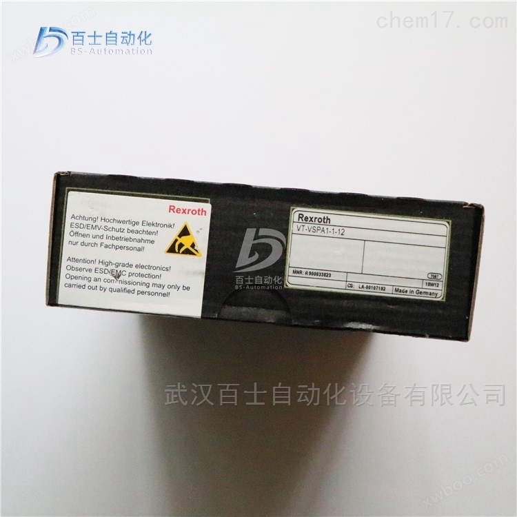
Proportional valve enlarged version VT-VSPA2-1-2X/V0/T1
NegotiableUpdate on 01/22
- Model
- Nature of the Manufacturer
- Producers
- Product Category
- Place of Origin
Overview
Proportional valve enlarged version VT-VSPA2-1-2X/V0/T1, German Rexroth proportional valve enlarged version, REXROTH proportional directional valve enlarged version, Rexroth proportional pressure valve enlarged version, REXROTH enlarged version
Product Details
Proportional valve enlarged version VT-VSPA2-1-2X/V0/T1The main products sold by Wuhan Baishi Automation Equipment Co., Ltd. are the German Rexroth proportional valve enlarged version, REXROTH proportional directional valve enlarged version, Rexroth proportional pressure valve enlarged version, and REXROTH enlarged version. They are original factory products and refuse high imitation and counterfeit goods. Customers can buy with peace of mind and use with peace of mind. *Common products available in stock, welcome new and old customers to inquire and purchase!


An amplifier is an electronic control unit suitable for open-loop proportional valves, rail mounted. The output current of the controller is proportional to the reference signal and independent of temperature changes and load impedance. The proportional electromagnet adopts PWM power supply, which can reduce the magnetic hysteresis of the valve and improve the control accuracy. On the front panel, there is an adjustment potentiometer for parameter setting, which is used to improve system performance. There are three models of this amplifier, which are used for single solenoid proportional valves, dual solenoid proportional valves, and single solenoid proportional valves with dual channel control. The high current and switching frequency (PWM) of each type of electronic control unit are different from each other, and can be selected according to the type of valve used (PWM).
The power supply needs to be rectified and filtered, and the maximum allowable peak voltage should not exceed 30V. The required power of the control circuit is related to the power supply voltage and the large output current of the circuit (determined by the control unit model). The usual required power is the product of the voltage value and the current value.
With the help of the+9 V regulating voltage of the power supply equipment, the control value voltage can be directly applied to the control value input 1 or through an external control value potentiometer. For this input, the following is valid:+9 V+100% 1) Control value input 2 is a differential input (0 to+10 V). With the help of DIL switch 2, it can be configured as a current input (4 to 20 mA or 0 to+20 mA). If the control value is fed forward by external electronic components with different reference potentials (e.g. through PLC), this input must be used. When applying or canceling the control value voltage, it is necessary to pay attention to disconnecting or connecting the two signal cables to the input.
Before transmitting control values, two control values will be accumulated and then supplied to a potentiometer accessible through the front panel, which serves as an attenuator and limits large control values.
The downstream ramp function generator generates a ramp shaped output signal based on a step input signal. With the help of two potentiometers, the time constant of the signal can be adjusted separately for the 'up' and 'down' slopes. The ramp time refers to a 100% step change in the control value, depending on the setting of DIL switch 2). This time may be around 1 s or 5 s. If less than 100% of the control value step change is provided to the input of the ramp function generator or the attenuator is effective, the ramp time will be correspondingly shortened.
The following content is valid for VT-VSPA1-1 type: With the external contact 'ramp up/down close', the up ramp time and down ramp time can be set to their respective small values (about 30 ms).
The following content is valid for VT-VSPA1K-1 type: With the external contact 'ramp off', the up ramp time and down ramp time can be set to their respective small values (about 30 ms).
Analog amplifier board VT-VSPA2-1-2X/... type
Suitable for controlling 4WRA type valves with nominal sizes 6 and 10... 2X, WRZ... 7X and 3DREP... 2X
→ Assembled in a printed circuit board with a European format of 100 x 160 mm structure, suitable for installation in a rack
→ Control value input: differential input ± 10 V; four control value inputs, starting voltage ± 10 V; current input 4 to 20 mA
→ Change the polarity of the internal control value signal through 24V input or jumper
→ By phase recognition (24V input) or ramp time startup (24V input)
Select slope time (option T5)
→ Switch the slope time range through jumper wires
→ Calibration of characteristic curves through adjustable step sizes and large values
→ Select input
→ "Slope on/off" input
→ Output signal "ready state"
→ Disconnectable measuring socket (option T5)
→ Polarity protection of power supply voltage
→ Power supply with AC/DC converter, without raising zero point
Note:
Use the amplifier card VT-VSPA2-1-2X as VT 3000-3X、VT 3006-3X、VT 3013-3X、VT3014-3X、VT 3017-3X、VT 3018-3X、VT 3026-3X、VT-VSPA2-1-1X/... When using VT-VSPA2-50-1X/... as an alternative, please follow the precautions regarding configuration and settings provided in Supplementary Information 30110-Z.
Proportional valve enlarged version VT-VSPA2-1-2X/V0/T1German Rexroth proportional valve enlarged version, REXROTH proportional directional valve enlarged version, Rexroth proportional pressure valve enlarged version, REXROTH enlarged version
Rexroth REXROTH analog circuit amplification version, European version standard
Valve amplifier for Rexroth proportional directional valve and proportional pressure valve
0811405081 VT-VSPA1-508-10/V0/RTP
0811405079 VT-VSPA1-525-10/V0/RTP
R901152628 VT-VSPA1-10-1X/V0/0
R901152637 VT-VSPA1-11-1X/V0/0
R901362646 VT-VSPA1-11-1X=V0/0
R900033823 VT-VSPA1-1-1X/
R900033823 VT-VSPA1-1-12
R900033823 VT-VSPA1-1-11
R900916996 VT-VSPA1-1-1X/001
R900934744 VT-VSPA1-1-1X/002/60SEC
R900940278 VT-VSPA1-1-1X/003/4-20MA/450MA
R900966500 VT-VSPA1-1-1X/004
R900978827 VT-VSPA1-1-1X/005
R978911748 VT-VSPA1-1-1X/ES43A8-1707
R978916539 VT-VSPA1-1-1X/ES43A8-3564/A2,A3
R978918946 VT-VSPA1-1-1X/S043A-1609
R978918205 VT-VSPA1-1-1X/SO43A-1616
R978919118 VT-VSPA1-1-1X/SO43A-1729
R900053778 VT-VSPA1K-1-1X/
R978914789 VT-VSPA1K-1-1X/SO43A-1668
R978839687 VT-VSPA1K-1-1X/SO43A-560-1
R900934739 VT-VSPA1K-1-1X/002/15SEC
R900934741 VT-VSPA1K-1-1X/002/60SEC
R900782310 VT-VSPA1-2-1X/V0/0
R900782310 VT-VSPA1-2-10/V0/0
R901002761 VT-VSPA1-2-1X/V0/A4
R901356608 VT-VSPA1-2-1X=V0/0
R901002090 VT-VSPA2-1-2X/V0/T1
R901002090 VT-VSPA2-1-20/V0/T1
R901002095 VT-VSPA2-1-2X/V0/T5
R901356606 VT-VSPA2-1-2X=V0/T1
R900033828 VT2000-5X/
Rexroth REXROTH analog circuit amplification module, European version standard
0811405126 VT-MSPA1-508-10/V0
0811405127 VT-MSPA1-525-10/V0
0811405106 VT-MSPA2-525-10/V0
Principles and Characteristics of Hydraulic Transmission Technology
1. Introduction to Hydraulic Transmission
Hydraulic transmission is a transmission method that uses liquid as the working medium to transfer energy and control. Hydraulic transmission and pneumatic transmission, also known as fluid transmission, are emerging technologies developed based on the principle of hydrostatic transmission proposed by Pascal in the 17th century. They are widely used in industrial and agricultural production.
2. Advantages of hydraulic transmission
(1) Due to its small size and light weight, the inertia force is relatively small. When suddenly overloaded or stopped, there will be no significant impact,
(2) Can smoothly and automatically adjust the traction speed within a given range, and can achieve infinite speed regulation;
(3) Easy to reverse direction, it can conveniently achieve the conversion between the rotation of the working mechanism and the linear reciprocating motion without changing the direction of motor rotation;
(4) The hydraulic pump and hydraulic motor are connected by oil pipes, and their spatial arrangement is not strictly limited to each other;
(5) Due to the use of oil as the working medium, the relative motion surfaces of the components can self lubricate, resulting in minimal wear and a long service life;
(6) Easy control and high degree of automation;
(7) Easy to implement overload protection.
Hydraulic transmission has many outstanding advantages, so its application is very extensive, such as plastic processing machinery, pressure machinery, machine tools, etc. for general industrial use, engineering machinery, construction machinery, agricultural machinery, automobiles, etc. for walking machinery, metallurgical machinery, lifting devices, roller adjustment devices, etc. for steel industry, flood control gates and dam devices, riverbed lifting devices, bridge beam control mechanisms, etc. for civil and hydraulic engineering; Power plant turbine speed control devices, deck lifting machinery for ships, bow doors, bulkhead valves, stern thrusters, special technology control devices, measuring buoys, lifting and rotating stages, etc.
3. Basic principles of hydraulic transmission
The basic principle of hydraulic transmission is to use pressurized oil as the working medium in a closed container to achieve energy conversion and power transmission. The liquid in it is called the working medium, usually mineral oil, and its function is similar to that of transmission components such as belts, chains, and gears in mechanical transmission. Hydraulic transmission utilizes Pascal's principle! Pascal's principle roughly states that when a force is applied to a liquid in a closed environment, the liquid will transmit this force in all directions! The magnitude of the force remains unchanged! Hydraulic transmission utilizes this physical property to apply a force to an object, and uses Pascal's principle to increase this force! Thus achieving the effect of lifting heavy objects!
Hydraulic transmission has also been widely used in the valve industry, such as machine tool manufacturing and processing equipment for valves, hydraulic testing equipment for valves, and hydraulic transmission devices for valves.

A loader is a widely used earthwork construction machinery in construction projects such as highways, railways, buildings, hydropower, ports, mines, etc. It is mainly used to shovel and load loose materials such as soil, sand, lime, coal, etc. It can also perform light excavation operations on ores, hard soil, etc. Changing to different auxiliary work devices can also be used for bulldozing, lifting, and loading and unloading other materials such as wood.
In road construction, especially in high-grade highways, loaders are used for filling and excavation of roadbed engineering, aggregate and loading of asphalt mixtures and cement concrete material yards. In addition, it can also carry out operations such as pushing soil, leveling the ground, and towing other machinery. Due to its advantages such as fast operating speed, high efficiency, good maneuverability, and easy operation, loaders have become one of the main models for earthwork construction in engineering projects.
The digging and loading/unloading operations of loaders are achieved through the movement of their working devices. The working device of a loader consists of a bucket, a boom, a connecting rod, a rocker arm, a rotary bucket cylinder, a boom cylinder, etc. The entire working device is hinged on frame 7. The bucket is hinged to the rotary bucket cylinder through connecting rods and rocker arms for loading and unloading materials. The boom is hinged to the frame and boom cylinder for lifting and lowering the bucket. The flipping of the bucket and the lifting of the boom are operated by hydraulic pressure.
The working device of the loader should be able to ensure that when the rotary bucket oil cylinder is locked or the boom oil cylinder is lifted or lowered, the connecting rod mechanism causes the bucket to move up and down or approach movement, in order to prevent the bucket from tilting and scattering materials; When the boom is in any position and the bucket rotates around the boom hinge point for unloading, the tilt angle of the bucket shall not be less than 45 °, and the bucket shall automatically level when the boom descends after unloading.
The main components of a loader include the engine, torque converter, gearbox, front and rear drive axles, abbreviated as the four major components Engine 2 There are three pumps on the torque converter, the working pump (supplying lifting and tipping pressure oil), the steering pump (supplying steering pressure oil), and the variable speed pump, also known as the walking pump (supplying torque converter and transmission pressure oil). Some models also have a pilot pump (supplying control valve pilot pressure oil) on the steering pump. 3. Working hydraulic oil circuit, hydraulic oil tank, working pump, multi way valve, lifting cylinder, and tipping cylinder Travel oil circuit: transmission oil pan oil, travel pump, one way to torque converter and one way to gear valve, transmission clutch 5 Drive: drive shaft, main differential, wheel reducer 6 Steering oil circuit: fuel tank, steering pump, steady flow valve (or priority valve), steering gear, steering cylinder 7 There are two types of gearboxes: integrated (planetary) and split (fixed shaft).
Similar Product Recommend