-
E-mail
980227448@qq.com
-
Phone
15307180902
-
Address
Room 2003, 20th Floor, Building A, Luojiashan Building, No.7 Luojiashan Road, Hongshan District, Wuhan City
Product Categories
Wuhan Baishi Automation Equipment Co., Ltd
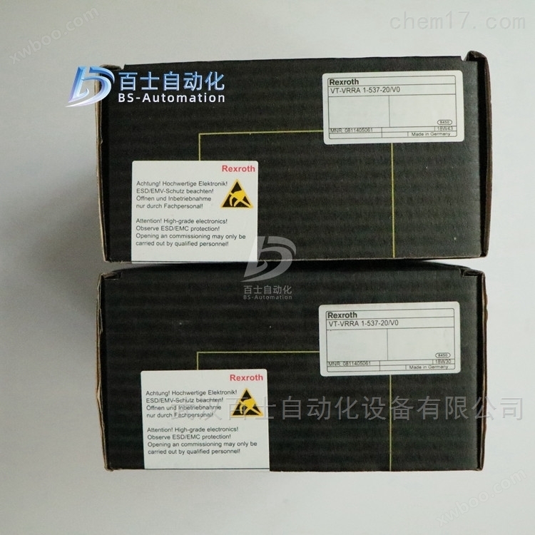

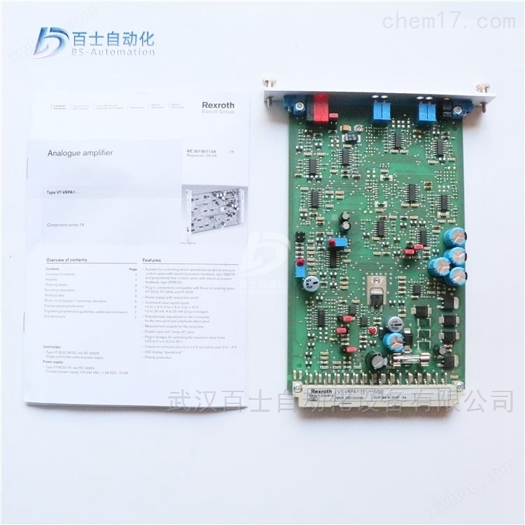
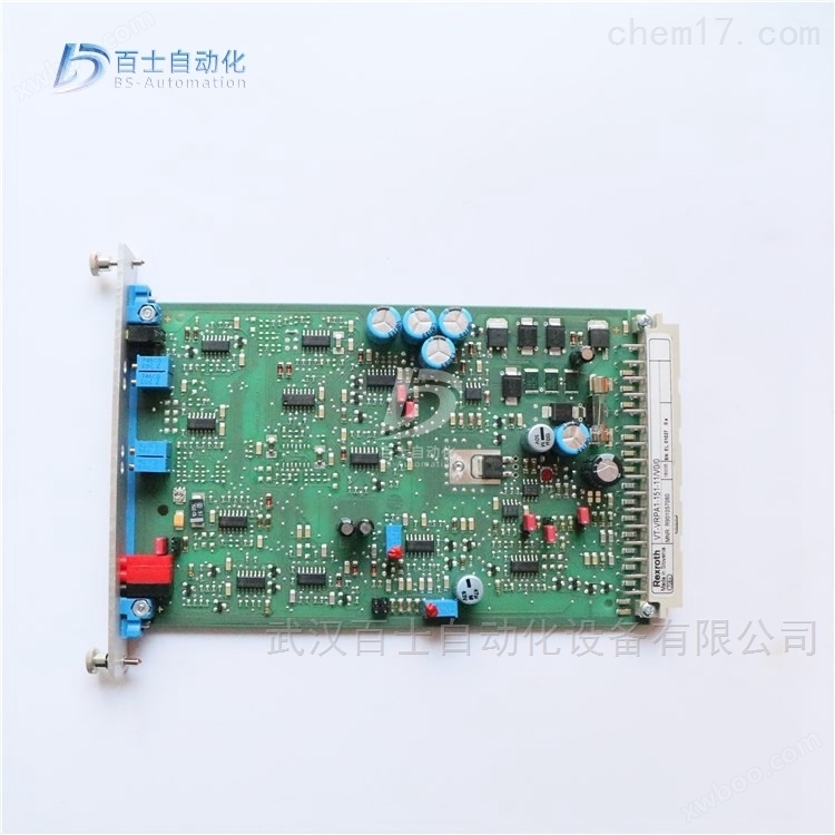

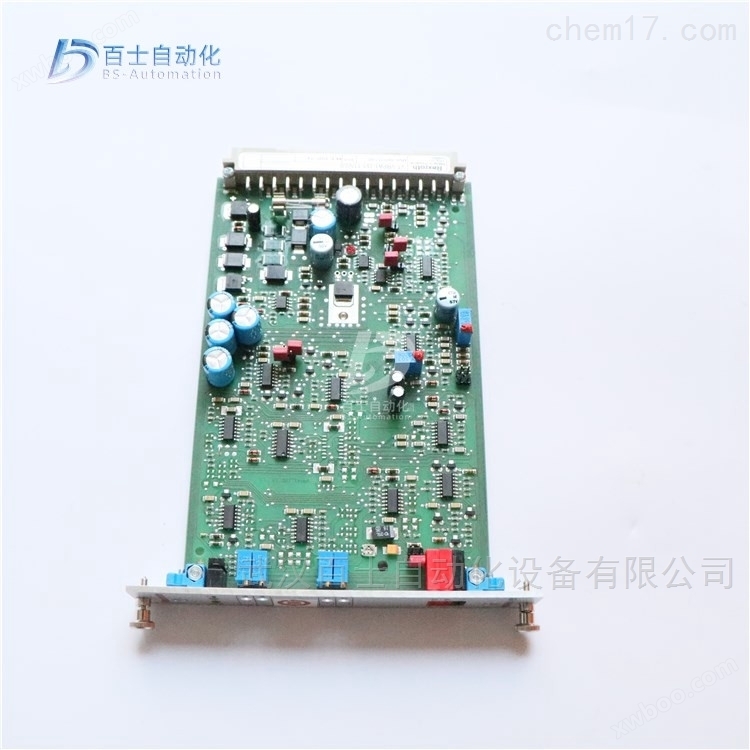
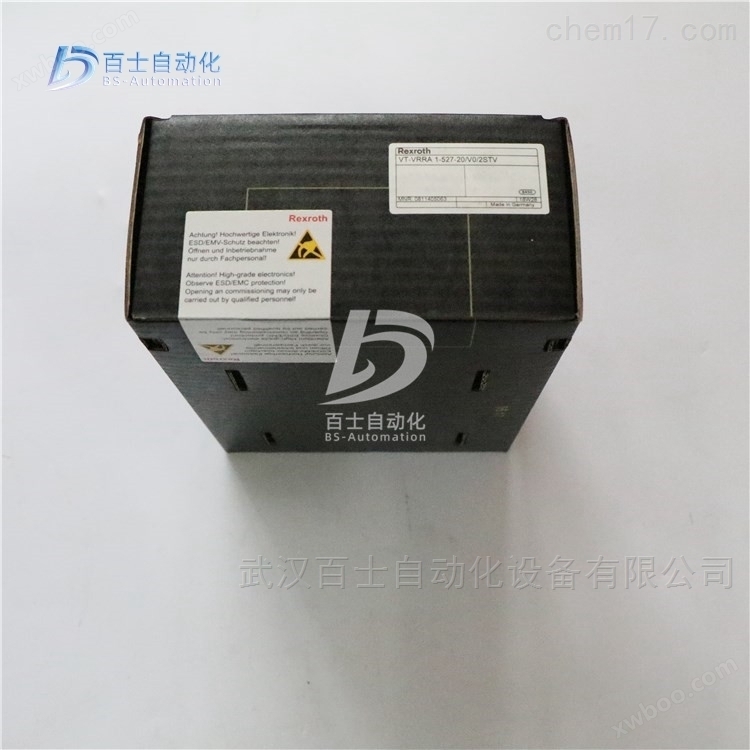
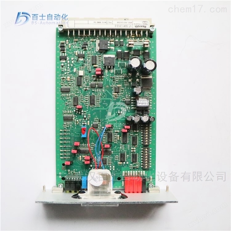
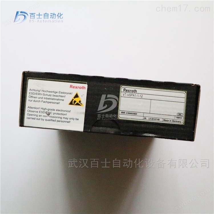
Analog circuit amplification version VT-VRPA2-1-1X/V0/T1
NegotiableUpdate on 01/22
- Model
- Nature of the Manufacturer
- Producers
- Product Category
- Place of Origin
Overview
Analog circuit amplification version VT-VRPA2-1-1X/V0/T1, Rexroth amplification version, REXROTH proportional valve amplification version, Rexroth proportional valve analog circuit amplification version, REXROTH amplifier
Product Details
Analog circuit amplification version VT-VRPA2-1-1X/V0/T1Rexroth amplification version, REXROTH proportional valve amplification version, Rexroth proportional valve analog circuit amplification version, REXROTH amplifier, Wuhan Baishi Automation Equipment Co., Ltd. specializes in selling products that are original from the factory and refuse high imitation counterfeit goods. Customers can buy and use with peace of mind. *Common products available in stock, welcome new and old customers to inquire and purchase!


The amplifier adopts a simple amplification principle, either amplifying the signal at the transmitting end or amplifying the attenuated signal at the receiving end. The amplification method at the receiving end is immediately abandoned because it amplifies interference during transmission, including crosstalk between internal signals. By using a specially designed VGA video cable as the transmission medium, devices that amplify the sending end can transmit VGA video signals from the computer for tens of meters.
Proportional electromagnets must have sufficient current to overcome spring force and hydraulic force output. Different manufacturers of proportional electromagnets typically require a current value ranging from 600-3000mA for large displacement, while industrial control standard signals are usually 0-5v/0-10v/-5-+5V/-10-+10v voltage signals or 0-20mA/4-20mA current signals. The control signal has weak load capacity and is not sufficient to drive the proportional electromagnet. The proportional valve amplifier plays a role in signal matching, receiving weak control signals and outputting the current required by the proportional electromagnet. At the same time, the proportional valve amplifier adds various necessary links, such as dead zone adjustment/gain adjustment/ramp time/flutter adjustment, etc. In short, a proportional valve amplifier is a signal matching device.
Electro hydraulic proportional valve is a hydraulic component that adopts proportional control technology and is located between switch type hydraulic valves and electro-hydraulic servo valves. It has been widely used in industrial production. The input electrical signals include analog and digital types, and can be used to control parameters such as position (angle), velocity (speed), acceleration (angular acceleration), pressure (pressure difference), force (torque), etc. Components such as electro-hydraulic proportional valves can form the following three types of control circuits and systems
(1) Electro hydraulic proportional pressure control circuit and system. For example, the electro-hydraulic proportional pressure control circuit for the hydraulic auxiliary system of the strip hot rolling mill coiler, the electro-hydraulic proportional pressure control circuit for the hydraulic push up system of the plate and strip rolling mill roll gap control, and the closed-loop electro-hydraulic proportional pressure control circuit for constant tension of the strip coiling equipment;
(2) Electric hydraulic proportional flow control circuit and system. For example, the electro-hydraulic proportional pressure control circuit used for the balance hydraulic system of the precision rolling mill of the strip hot rolling mill, the electro-hydraulic proportional control circuit used for the micro feed of the machine tool, the electro-hydraulic proportional control circuit used for the synchronization of the folding plate machine of the spinning machine, and the electro-hydraulic proportional control circuit used for the elevator;
(3) Electro hydraulic proportional multi parameter control circuit and system. For example, the electro-hydraulic proportional pressure control circuit used for the hydraulic system of the precision rolling and roll changing in the hot strip rolling mill, the proportional control circuit using the wI type valve core for the vertical configuration of the hydraulic cylinder, and the speed and acceleration/deceleration control circuit for the hot rolled steel coil stepper chain conveyor.
Electro hydraulic proportional valve is a component that generates corresponding actions based on the input voltage signal of the proportional solenoid inside the valve, causing displacement of the valve core and changes in the size of the valve port, thereby completing pressure and flow output components proportional to the input voltage. The displacement of the valve core can also be fed back in mechanical, hydraulic, or electrical forms. The electro-hydraulic proportional valve has various advantages, such as diverse forms, easy composition and use of electrical and computer control of various electro-hydraulic systems, high control accuracy, flexible installation and use, and strong anti pollution ability. Its application fields are increasingly expanding. In recent years, the development and production of plug-in proportional valves and proportional multi way valves have fully considered the characteristics of engineering machinery use, and have functions such as pilot control, load sensing, and pressure compensation. Its appearance is of great significance for improving the overall technical level of mobile hydraulic machinery. Especially in terms of electronic control pilot operation, wireless remote control, and wired remote control operation, it has demonstrated its good application prospects.
Analog circuit amplification version VT-VRPA2-1-1X/V0/T1Rexroth amplification version, REXROTH proportional valve amplification version, Rexroth proportional valve analog circuit amplification version, REXROTH amplifier
Rexroth REXROTH analog circuit amplification version, European version standard
0811405095 VT-VRPA1-527-10/V0
0811405096 VT-VRPA1-527-10/V0/PV
0811405098 VT-VRPA1-527-10/V0/QV
0811405097 VT-VRPA1-537-10/V0/PV
0811405099 VT-VRPA1-537-10/V0/QV
0811405101 VT-VRPA1-527-10/V0/PV-RTP
0811405103 VT-VRPA1-527-10/V0/QV-RTP
0811405100 VT-VRPA1-527-10/V0/RTP
0811405102 VT-VRPA1-537-10/V0/PV-RTP
0811405104 VT-VRPA1-537-10/V0/QV-RTP
081145074 vt -vrppa1-527-20 / V0 / RTs -2 / 2V
R978022097 VT-VRPA1-100-1X/SO43A-466B
R901009038 VT-VRPA1-100-1X/V0/0
R901057058 VT-VRPA1-150-1X/V0/0
R901057060 VT-VRPA1-151-1X/V0/0
R901057060 VT-VRPA1-151-11/V0/0
R901057060 VT-VRPA1-151-12/V0/0
R900952202 VT-VRPA1-50-1X/
R900619297 VT-VRPA1-50-1X/001 FEDERLEIST 32POLIG F
R978911504 VT-VRPA1-50-1X/SO43A-472B
R900952204 VT-VRPA1-51-1X/
R979810986 VT-VRPA1-51-1X/ SO41-7519
R978031853 VT-VRPA1-51-1X/SO43A-1828
R900952205 VT-VRPA1-52-1X/
R900979887 VT-VRPA2-1-1X/V0/T1
R900979887 VT-VRPA2-1-11/V0/T1
R900979885 VT-VRPA2-1-1X/V0/T5
R900979889 VT-VRPA2-2-1X/V0/T1
R900979888 VT-VRPA2-2-1X/V0/T5
R900067617 VT-VRM1-1-1X/
At present, there are two main forms of steel bar cutting machines: mechanical cutting machines and hydraulic cutting machines
Mechanical cutting machines mainly use the movement of cams to cut steel bars, while hydraulic cutting machines mainly use hydraulic systems to provide power for the machine to work. Compared with these two types of cutting machines, hydraulic cutting machines have more obvious advantages, such as stable performance and low noise, which provide favorable conditions for the wide application and creativity of hydraulic cutting machines. From the current development trend, hydraulic cutting machines have overcome some of the shortcomings of the past, with significant improvements in performance such as shear rate, speed, and error. This design focuses on the hydraulic system pump station of the cutting machine. The system adopts measures such as electromagnetic directional valves, stacked pressure reducing valves, and pressure sensors to ensure smooth operation, low energy consumption, and high safety and reliability of the hydraulic system.
Due to the many advantages of hydraulic technology, it has been widely applied from general transmission to precision control. In the mechanical industry, 85% of machine tool transmission systems currently use hydraulic transmission and control, such as grinding, milling, planing, pulling, and combination lathes; In construction machinery, hydraulic transmission is commonly used, such as excavators, tire loaders, car starters, track bulldozers, self-propelled loaders, graders, rollers, etc; In agricultural machinery, it is currently used in combine harvesters, tractors, and tool suspension systems; In the automotive industry, hydraulic brakes, hydraulic self dumping, and fire ladders are widely used; In the metallurgical industry, such as electric furnace control system, steel rolling mill control system, hand furnace loading, converter control, blast furnace control, etc; In the textile industry, such as injection molding machines, rubber vulcanizing machines, paper machines, printing machines, textile machinery, etc; In the shipbuilding industry, such as fully hydraulic dredgers, salvage boats, oil platforms, wing boats, hovercrafts, and ship auxiliary equipment. Hydraulic technology can be used in all engineering fields and in any situation where mechanical equipment is present. The range of applications and equipment is becoming wider and more diverse
A bending machine is a machine capable of bending thin plates. Its structure mainly includes a bracket, a worktable, and a clamping plate. The worktable is placed on the bracket, and the worktable consists of a base and a pressure plate. The base is connected to the clamping plate through a hinge, and the base consists of a seat shell, a coil, and a cover plate. The coil is placed in a recess of the seat shell, and the top of the recess is covered with a cover plate. When in use, the coil is energized by a wire, which generates an attractive force on the pressure plate, thereby achieving the clamping of the thin plate between the pressure plate and the base. Due to the use of electromagnetic force clamping, the pressure plate can be made into various workpiece requirements, and can also process workpieces with side walls, making the operation very simple.
The hydraulic bending machine includes a bracket, a worktable, and a clamping plate. The worktable is placed on the bracket, and the worktable consists of a base and a pressure plate. The base is connected to the clamping plate through a hinge. The base consists of a seat shell, a coil, and a cover plate. The coil is placed in a recess of the seat shell, and the top of the recess is covered with a cover plate.
When in use, the coil is energized by a wire, which generates an attractive force on the pressure plate, thereby achieving the clamping of the thin plate between the pressure plate and the base. Due to the use of electromagnetic force clamping, the pressure plate can be made into various workpiece requirements and can also process workpieces with side walls. The bending machine can meet the needs of various workpieces by replacing the bending machine mold.
Bending machines are divided into manual bending machines, hydraulic bending machines, and CNC bending machines. Manual bending machines are divided into mechanical manual bending machines and electric manual bending machines. Hydraulic bending machines can be further divided into torsional axis synchronization, machine hydraulic synchronization, and electro-hydraulic synchronization according to synchronization methods. Hydraulic bending machines can be divided into upward and downward movements according to their motion modes.

Composition of hydraulic transmission system
1. Hydraulic power components
A device that converts the mechanical energy of a power unit into hydraulic energy, providing pressure oil for the hydraulic transmission system and serving as its power source. For example, hydraulic pumps.
1.1 Hydraulic pump
The hydraulic pump is the power component of the hydraulic system, which converts the mechanical energy of the prime mover into the pressure energy of the liquid. It refers to the oil pump in the hydraulic system, which provides power to the entire hydraulic system. The structural forms of hydraulic pumps generally include gear pumps, vane pumps, and plunger pumps.
1.2 Gear pump
Gear pump is a pump that relies on two or more gears sealed in a housing to transport liquids through the change in working space volume generated during the meshing process. The concept of a gear pump is very simple, that is, its basic form is two gears of the same size meshing and rotating with each other in a tightly fitting housing. The interior of this housing is similar to an "8" shape, and two gears are installed inside, with the outer diameter and both sides of the gears tightly fitting with the housing. The material from the extruder enters the space between two gears at the suction port and fills it. It moves along the shell with the rotation of the teeth and is discharged when the two teeth mesh. The phenomenon of oil entrapment requires the gear pump to operate smoothly, and the meshing overlap of the gears must be greater than 1. Therefore, there are always two pairs of gears meshing simultaneously, and a portion of the oil is trapped between the closed chambers enclosed by the two pairs of gear teeth. This closed chamber begins to follow
The rotation of the gear gradually decreases and then gradually increases again. The decrease in the volume of the enclosed chamber will cause the trapped oil to be squeezed and generate high pressure, which will be squeezed out from the gaps, causing the oil to heat up and causing additional loads on the components. The increase in the volume of the enclosed chamber will also cause local vacuum, resulting in the separation of dissolved gases in the oil and the formation of gas pockets. These will all generate strong vibrations and noise, which is the phenomenon of fatigue in gear pumps.
Harm: When the radial unbalance force is large, it can cause the shaft to bend, the tooth tip to come into contact with the housing, and accelerate the wear of the bearing, reducing its service life.
Method for eliminating trapped oil: Usually, unloading slots are opened on both sides of the cover plate, so that when the volume of the closed chamber is small, it is connected to the oil pressure chamber through the unloading slot on the left, and when the volume increases, it is connected to the oil suction chamber through the unloading slot on the right.
1.3 Vane pump
A vane pump is a hydraulic machine that converts the mechanical energy of a power machine into water energy (potential energy, kinetic energy, pressure energy) through the rotation of the impeller.
When the rotor of the vane pump rotates, the tips of the blades are tightly attached to the inner surface of the stator under the action of centrifugal force and pressure oil. The working volume formed by the two blades and the inner surfaces of the rotor and stator first absorbs oil from small to large, and then discharges oil from large to small. When the blades rotate once, they complete two oil suction and discharge operations.
1.4 Piston pump
A plunger pump utilizes the reciprocating motion of a plunger within the pump cylinder to create a volume change between the plunger and the pump wall, allowing for repeated suction and discharge; A pump that releases liquid and increases its pressure.
A plunger pump is an important device in hydraulic systems. It relies on the reciprocating motion of the plunger in the cylinder body to change the volume of the sealed working chamber to achieve oil suction and pressure. Piston pumps have the advantages of high rated pressure, compact structure, high efficiency, and convenient flow regulation. They are widely used in high-pressure, high flow, and flow regulation applications, such as hydraulic presses, engineering machinery, and ships.
Similar Product Recommend