-
E-mail
ouyangchao@qh-ndt.com
-
Phone
15275259479
-
Address
No. 12, Lane 555 Tianzhu Road, Jiading District, Shanghai, 2004
Product Categories
Qianhu Testing (Shanghai) Co., Ltd


Ultrasonic flaw detector phased array wedge block
NegotiableUpdate on 01/23
- Model
- Nature of the Manufacturer
- Producers
- Product Category
- Place of Origin
Overview
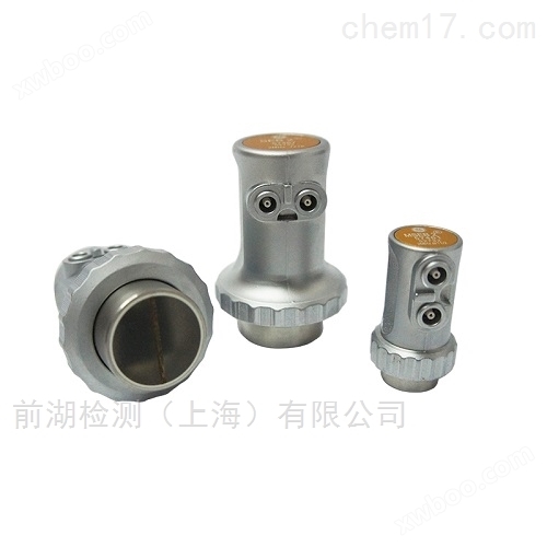
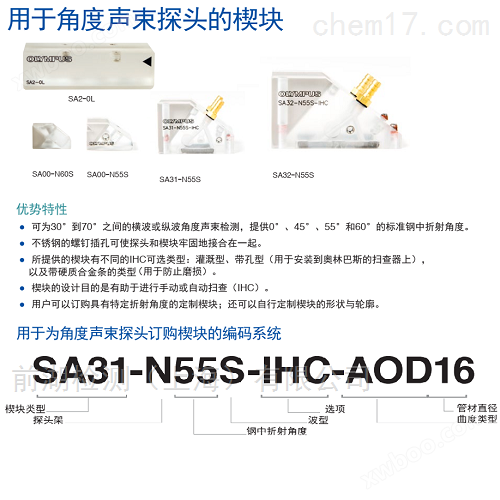
Olympus Ultrasonic Flaw Detector Phased Array Wedge SA00-N60S SA00-N55S SA2-0L SA31-N55S SA32-N55S Wedge for Angle Beam Probe
Product Details
OlympusUltrasonic flaw detectorPhased array wedge blockAt 00 -n 60 s at 00 -n 55 s
SA2-0L SA31-N55S SA32-N55S Wedge block for angle beam probe
Advantages and Characteristics
●can be30° to70Detection of transverse or longitudinal wave angle beams between degrees, providing0°45°55° and60Refractive angle in standard steel.
●The stainless steel screw socket can firmly connect the probe and wedge block together.
●The wedges provided have different typesIHCOptional types: irrigation type, hole type (for installation on Olympus scanners), and type with hard alloy strip (for wear prevention).
●The design purpose of the wedge block is to facilitate manual or automatic scanning(IHC).
●Users can order customized wedges with specific refractive angles; You can also customize the shape and contour of the wedge block by yourself.
Wedge type
SA=wedge block for A-type probe
SAWS=Wedge block for AWS type probe
SNW=wedge block for NW type near wall probe
SPWZ=Wedge block for PWZ type PipeWIZARD probe
Probe holder
N=Normal
L=Side (90 ° oblique angle)
DN=twin normal
Refraction angle in steel
0 = 0°
55 = 55°
60 = 60°
Wave pattern
S=transverse wave
L=longitudinal wave
option
IHC=Irrigation, Scanner Holes, and Hard Alloy Anti Wear Nails
IHC-C=Irrigation, Scanner Holes, and Composite Anti Wear Nails
IHS=irrigation, scanner holes and stainless steel frames
Curvature type
AOD=axial outer diameter (circumferential scan)
COD=circumferential outer diameter (axial scan)
Introduction to phased array technology
The distinguishing feature of phased array ultrasonic testing from other technologies is that it can excite a single chip in a multi chip probe through computer control (amplitude and delay). By exciting multiple piezoelectric composite material chips through software, a focused ultrasonic beam can be generated by dynamically changing the parameters of the beam, such as angle, focal length, and focal size, during the emission process. To generate a sound beam through active interference in phase, multiple active chips of the probe need to be triggered with minimal time difference. Similarly, the echo reflected from the expected focal point will touch different chips of the probe with a computable time offset. Before summarizing the echo signals received by each chip, it is necessary to perform time offset calculations on these echo signals. The summary result is to generate an A-scan, which highlights the response signal from the desired focus and weakens the signal from other parts of the tested sample.
Use software to control the angle, focal length, and focal size of the sound beam
To generate an ultrasound beam, it is necessary to probe at very different times with minimal differences
Pulse excitation is performed on different chips of the head. By controlling the time delay between probe chips, sound beams with different angles, focal lengths, and focal sizes can be generated. The echo reflected from the expected focal point will touch different chips of the probe with a computable time offset. Before summarizing the echo signals received by each chip, it is necessary to perform time offset calculations on these echo signals. The result of signal aggregation is to generate an A-scan. This A-scan will highlight the response signal from the desired focus and weaken various echoes from other parts of the material.
Multi angle detection can be achieved using a single, compact polycrystalline probe controlled electronically
Conventional UT testing requires the use of multiple different probes. A single phased array (PA) probe can be configured according to application requirements to generate different angles and focal points in a sequential manner.
Complete high-speed scanning without moving parts
Although phased array technology processes many signals from multi chip probes, it is important to note that the resulting signal is a standard radio frequency (RF) signal (or A-scan) that is identical to any conventional system using a fixed angle probe. This signal, like any A-scan from a conventional UT system, can be evaluated, processed, filtered, and an image generated. The B-scan, C-scan, and D-scan created based on A-scan are also similar to the images generated by conventional systems. The difference between them is that phased array systems can use a single probe to complete multi angle detection. Multi channel transmission can also complete scanning without moving the probe: focusing the sound beam
Created from several chips of a long-range array probe containing many chips. Then the sound beam is moved (or multiplexed) to other chips to perform high-speed scanning of the workpiece along the scanning axis without moving the probe. This way, the probe can perform more than one scan at different detection angles. This principle can be applied to the detection of planar workpieces using linear phased array probes, as well as to the detection of pipes and bars using circular phased array probes.
OlympusUltrasonic flaw detectorPhased array wedge blockAt 00 -n 60 s at 00 -n 55 s


|
|||||||||