-
E-mail
1119594485@qq.com
-
Phone
15152325661
-
Address
95-6 Tongtai Avenue, Jinhu County
Product Categories
Jinhu Tianxiang Instrument Co., Ltd
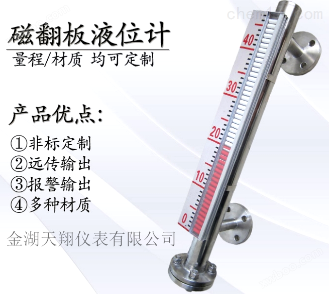
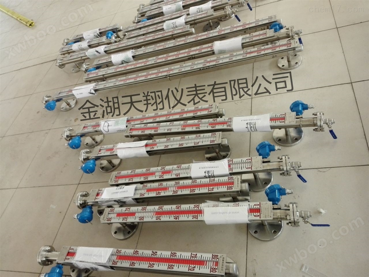
Selection of Purified Water Level Gauge
NegotiableUpdate on 01/22
- Model
- Nature of the Manufacturer
- Producers
- Product Category
- Place of Origin
Overview
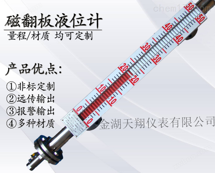
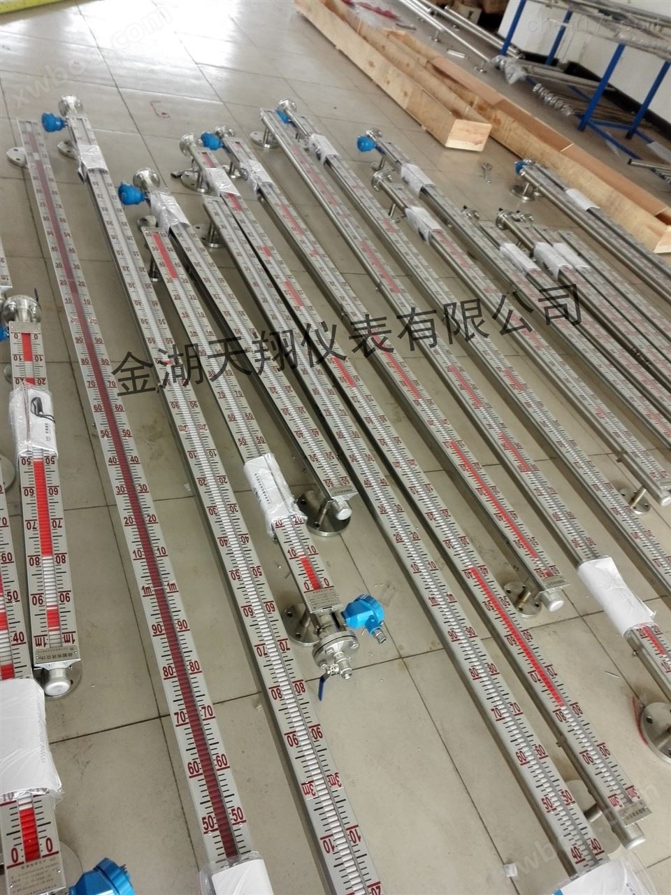
Please refer to the following content for the selection of purified water level gauge. Purified water level gauge is a level gauge developed by our company to measure the height of liquid in storage tanks. This product is widely used in fields such as chemical and food factories, with high measurement accuracy and long service life.
Product Details
Selection of Purified Water Level Gauge--Zhang Hao, Marketing Department of Jinhu Tianxiang Instrument Co., Ltd

Overview of Purified Water Level Gauge
The structural principle of the purified water level gauge is shown in the diagram. The body is a connecting tube connected to the user container through a flange. There is a magnetic float inside the connecting tube that rises and falls with the level of the liquid. An indicator composed of a flip column is fixed outside the tube body. The flip column is composed of red and white colors, and it is white before the liquid level rises. When the liquid level rises, the magnetic float follows suit and drives the flip column to rotate through magnetic coupling180The degree, when translated into red, indicates the liquid level. The red and white boundaries represent the height of the liquid level inside the container.
A drain valve can be installed below the magnetic flap level gauge. When needed, the drain valve can be opened to remove dirt. And there is an exhaust bolt above, which can be loosened to remove air when needed.
On one side of the magnetic flap level gauge tube, upper and lower limit alarms can be installed according to user needs. There are two types of alarms:
(1)XGType alarm: The alarm is equipped with a dynamic (normally open) reed switch. When the float in the main tube rises (falls) with the liquid level to the alarm set point, the magnetic steel inside the float will close the reed switch and emit a contact signal. When the float leaves the alarm point with the liquid level rising (falling), the signal at that point will automatically cancel.
(2)XJType alarm: The alarm is equipped with a magnetic coupling driven alarm insideswitchWhen the float crosses the upper and lower limit alarm points, it drives the alarm switch to emit a signal, achieving liquid level alarm or control. The alarm switch has one normally open contact and one normally closed contact. And it has a memory function that does not restore the liquid level and does not eliminate the alarm signal, which is beneficial for the production processsafetyThe operation played a very important role.
On the other side of the magnetic flap level gauge tube, an electric remote transmitter can be installed according to user needs to convert the liquid level height into a standard current signal output,To provide liquid level signal output,For remote transmission of liquid level signals to the secondary systeminstrumentPerform instruction control and detection.


Purified water level gaugeProduct principle:
1. Basic type
According to the principle of buoyancy, the float moves up and down in the measuring tube with the rise and fall of the liquid level, and the permanent magnet steel inside the float is coupledcooperationDrive the red and white flip columns to flip 180 °. When the liquid level rises, the flip column changes from white to red, and when it falls, it changes from red to white, thus achieving liquid level indication.
2. Electric remote transmission
Install a transmitter on the float level gauge, move the float up and down, and use magnetic coupling to sequentially move the measuring elements inside the guide rod to obtain resistance signal changes, convert them into standard signal outputs of 0-10mA or 4-20mA, and connect them with display instruments or computers to achieve remote transmission.
3. Upper and lower limit switch output
A controller is installed on the liquid level gauge riser at the upper and lower limit positions set by the user. The controller is equipped with a self holding reed switch, which uses a magnetic float to move with the liquid level to activate the spring switch and achieve alarm or limit control.

System composition and wiring
1. Upper and lower limit switch output
Composed of a self retaining reed switch and converter, the reed switch and converter are installed on site and in the control room respectively, with three pairs of contact switches provided by the converter.
2. Electric remote transmission
It consists of two parts: the measuring unit and the transmitting unit.
3. Intrinsic safety explosion-proof
A with intrinsic safety explosion-proof, upper and lower limit switch output type
The explosion-proof switch consists of a reed switch and a safety barrier with relay contacts, which can directly provide users with a pair of normally open or normally closed contacts. If users require more touchpoints, they can place special design orders. (Figure 3)
B-belt security explosive remote transmission type
Suitable for use in π - class electrical equipment (factory use), C-class gas, high surface temperature group T4 (135 ℃). (Figure 4)
C Precautions for use
① The transmitter housing is equipped with an external grounding, which must be reliably grounded when used by the user.
② The use of safety barriers should comply with the relevant instructions.
③ Connection between transmitter and safety barrier intrinsic safety endcableFor a two core shielded cable, the cross-sectional area of the core wire is greater than 0.5m, and the allowable distributed capacitance of the cable is 0.8 μ F.

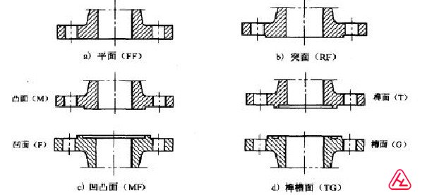
Purified Waterlevel gaugeSealing surface type
Purified water level gaugefeature
The flip column shell is made of polyester and high-temperature ceramics, and is resistant to high temperatures.
Suitable for measuring the liquid level and interface of liquid media in containers. In addition to on-site instructions, remote transmitters, alarm switches, and control switches can also be equipped with complete detection functions.
The indication is novel, the reading is intuitive and eye-catching, and the direction of the observation indicator can be changed according to the user's needs.
The measurement range is large and not limited by the height of the storage tank.
The indicator mechanism is isolated from the tested medium, resulting in good sealing, high reliability, and safe use.
Simple structure, easy installation, and low maintenance costs.
Corrosion resistance, no need for power supply, and good explosion-proof performance.
The flip column magnetic steel adopts imported demagnetized materials, which can operate reliably under high temperature and high pressure conditions.
Measurement range: 300-15000mm
Accuracy: ± 10mm, ± 20mm
● Column flipping diameter: 9mm, 16mm
● Working pressure: ≤ 4.0MPa (can be designed separately for pressures above 4.0MPa) Anti corrosion type ≤ 1.0MPa
● Medium density: ≥ 0.45g/cm3
● Medium density difference ≥ 0.15g/cm3 (measurement boundary)
● Medium temperature: -20 to+250 ℃ (special requirements must reach 450 ℃)
● Medium viscosity: ≤ 0.4Pa? S. For media with high viscosity or media that are prone to crystallization at low temperatures, a heated jacket type liquid level gauge can be selected according to user requirements.
Environmental vibration: frequency ≤ 25Hz, amplitude ≤ 0.5mm
● Follow speed: ≤ 0.08m/s
Our factory's factory connection flange size: DN20, PN0.6 (metric pipe), can also be customized according to user requirements.
Please refer to the relevant content in this sample for the main technical parameters of the remote transmission supporting instruments.
If there are special requirements, they can be discussed during ordering.
Purified water level gaugeClassification and Applicable Scenarios:
1. Ordinary type: suitable for low, medium, and high pressure applications without special anti-corrosion requirements.
2. Vacuum type: suitable for ultra-low, ultra-high temperature, low, medium, high pressure, and no special anti-corrosion requirements.
3. Frost proof type: suitable for low temperature, low, medium, high pressure, and occasions without special anti-corrosion requirements.
4. Underground type: suitable for underground or top perforated storage tanks, where the medium does not move much.
5. Jacket type: suitable for situations that require insulation or cooling, low, medium, and high pressure, and no special anti-corrosion requirements.
6. Inner lining type: PTFE or other lining, suitable for low, medium, and high pressure applications with special anti-corrosion requirements.
7. Anti corrosion type: made of PP or PVC material, suitable for corrosion resistant applications at room temperature and atmospheric pressure.
Selection of Purified Water Level Gaugeparameter
|
Installation type content |
side-mounted |
Top mounted |
|
Installation spacing |
500,800,1100,1400,1700, |
500,800,1100,1400,1700, |
|
work pressure |
0.6,1.6,2.5,4.0MPa |
0.6,1.6,2.5MPa |
|
medium density |
≥ 0.5g/cm 3 |
≥ 0.76g/cm 3 |
|
flange connection |
stainless steel |
Flange 20-40 (D N 20 P N 4.0) |
Flange 200-25 (D N 200 P N 2.5) |
ABS |
Flange 20-10 (D N 20 P N 1.0) (GB9119-88) |
Flange 200-6 (D N 200 P N 0.6) |
|
main material |
ABS (working pressure 0.6MPa) 1Cr18Ni9T |
||
medium temperature |
-40 ℃ ~100 ℃ (ABS: -40 ℃ ~80 ℃ ) |
||
ambient temperature |
-40 ℃ ~+70 ℃ |
||
indication error |
± 10mm |
||
medium viscosity |
≤ 1st(10 - 4 m/s) |
||
Upper and lower limit switches |
1. Control sensitivity: 10mm |
||
Continuous display of electric remote transmission |
1. Accuracy: ± 1.5% |
||
Installation method of purified water level gauge
1: We must first understand the operating environment of our equipment and what the measuring medium is. Even if we do not know what material is needed, our company can determine the material used for the equipment based on the medium.
2: When equipped with remote transmission supporting instruments, the following measures should be taken: the remote transmission supporting instruments should be tightly attached to the main pipe of the liquid level gauge and fixed with stainless steel clamps (iron is prohibited); The sensing surface on the remote transmission supporting instrument should face and be closely attached to the main pipe; The zero position of the remote transmission supporting instrument should be on the same horizontal line as the zero position indication of the liquid level gauge; The connection between remote transmission supporting instruments and display instruments or industrial control computers shall be separately laid through protective pipes or shielded two core cables; After the wiring holes of the junction box are laid, it is required to be well sealed to prevent rainwater, moisture, and other factors from entering and causing the remote transmission supporting instruments to malfunction. The junction box should be promptly covered after maintenance or debugging is completed.
3: According to the condition of the medium, the main pipe should be cleaned irregularly to remove impurities;
4: For exceeding a certain length (ordinary type>3Rice, anti-corrosion type2The liquid level gauge (meter) needs to be reinforced with a middle flange or ear hook as a fixed support to increase strength and overcome its own weight;
5: Installation position: It should avoid or be far away from the inlet and outlet of the material medium to prevent rapid changes in the local area of the material fluid, which may affect the accuracy of liquid level measurement;
6: When debugging, the upper inlet valve should be opened first, and then the lower valve should be slowly opened to allow the medium to enter the main pipe smoothly (during operation, the medium should avoid rapid impact on the float, causing the float to fluctuate dramatically and affecting the display accuracy). Observe whether the magnetic red and white balls flip normally, then close the lower inlet valve, open the drain valve, and let the liquid level in the main pipe decrease. Follow this method three times, if it is normal, it can be put into operation (except for corrosive and other special liquids); There are also other names on the market, such as magnetic flap level gauge, magnetic flap column level gauge, etc. But the parameters they need to know for ordering are certain, such as the anti-corrosion material required for corrosive media, and the anti-corrosion level varies equally according to the corrosiveness level of the media.
installation diagram 
Precautions
1.For those exceeding a certain length (ordinary type)>3Rice, anti-corrosion type>2Meter level gauge.
2.The installation position should avoid or be far away from the inlet and outlet of the material medium to prevent rapid changes in the local area of the material fluid, which may affect the accuracy of liquid level measurement;
3.When equipped with remote transmission instruments, the following measures should be taken:
4.The remote transmission supporting instruments should be tightly attached to the main pipe of the liquid level gauge and fixed with stainless steel clamps (iron is prohibited);
5.The sensing surface on the remote transmission supporting instrument should face and be closely attached to the main pipe;
6.When debugging, the upper inlet valve should be opened first, and then the lower valve should be slowly opened to allow the medium to enter the main pipe smoothly (during operation, the medium should avoid rapid impact on the float, causing the float to fluctuate dramatically and affecting the display accuracy). Observe whether the magnetic red and white balls flip normally, then close the lower inlet valve, open the drain valve, and let the liquid level in the main pipe decrease. Follow this method three times, if it is normal, it can be put into operation (except for corrosive and other special liquids);
7.The main tube should be periodically cleaned to remove impurities based on the condition of the medium.