-
E-mail
1119594485@qq.com
-
Phone
15152325661
-
Address
95-6 Tongtai Avenue, Jinhu County
Product Categories
Jinhu Tianxiang Instrument Co., Ltd
Common knowledge of fuel level gauge
NegotiableUpdate on 01/22
- Model
- Nature of the Manufacturer
- Producers
- Product Category
- Place of Origin
Overview
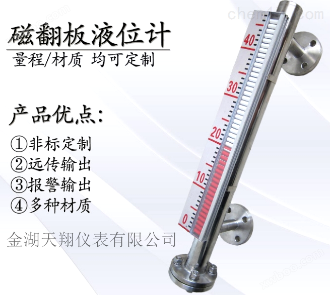
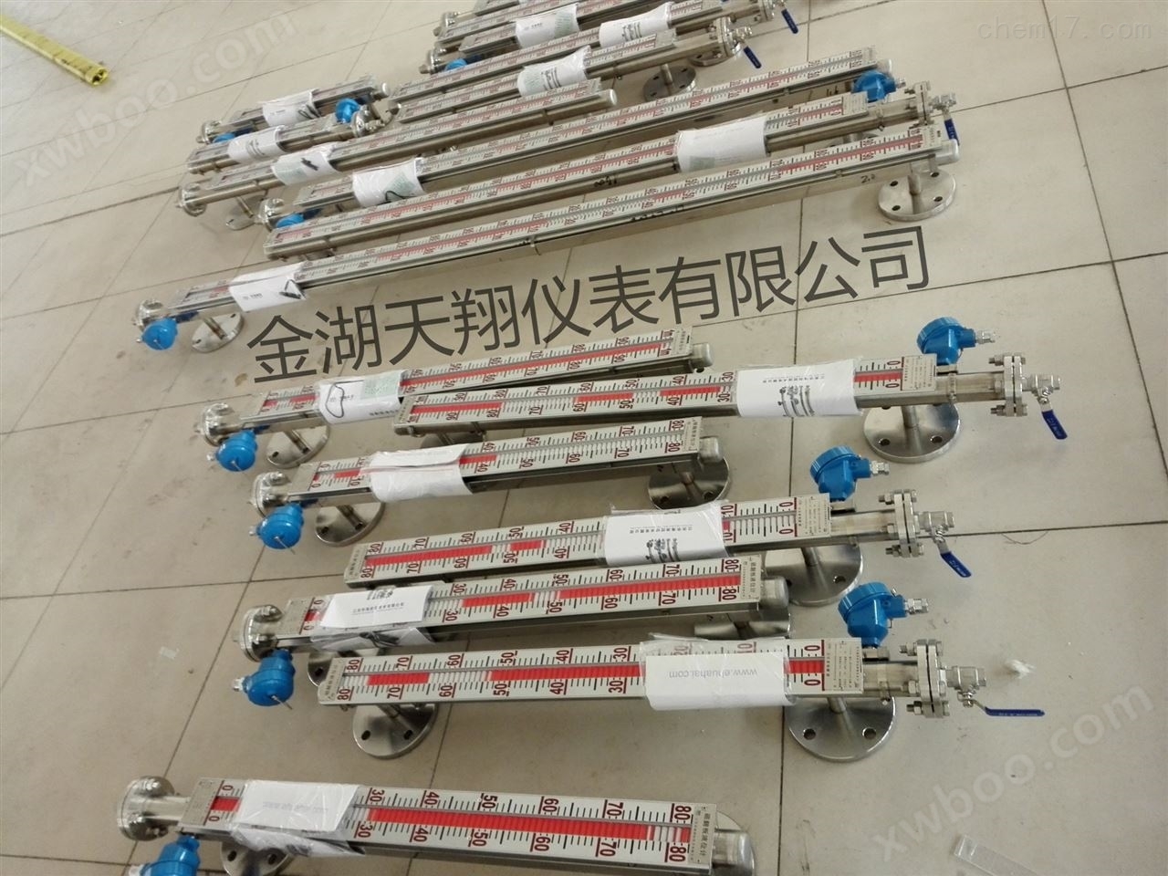
Please refer to the following content for common knowledge of fuel level gauge. Fuel level gauge is a level gauge developed by our company to measure the height of liquid in storage tanks. This product is widely used in fields such as chemical and food factories, and has the characteristics of high measurement accuracy and long service life.
Product Details
Common knowledge of fuel level gauge--Zhang Hao, Marketing Department of Jinhu Tianxiang Instrument Co., Ltd

Common knowledge of fuel level gauge
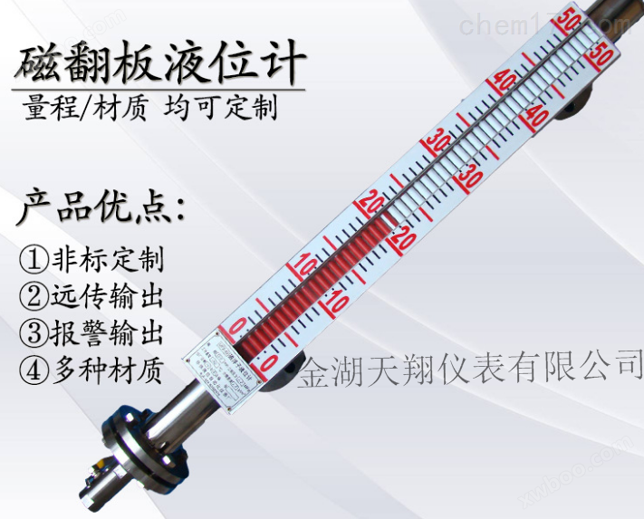
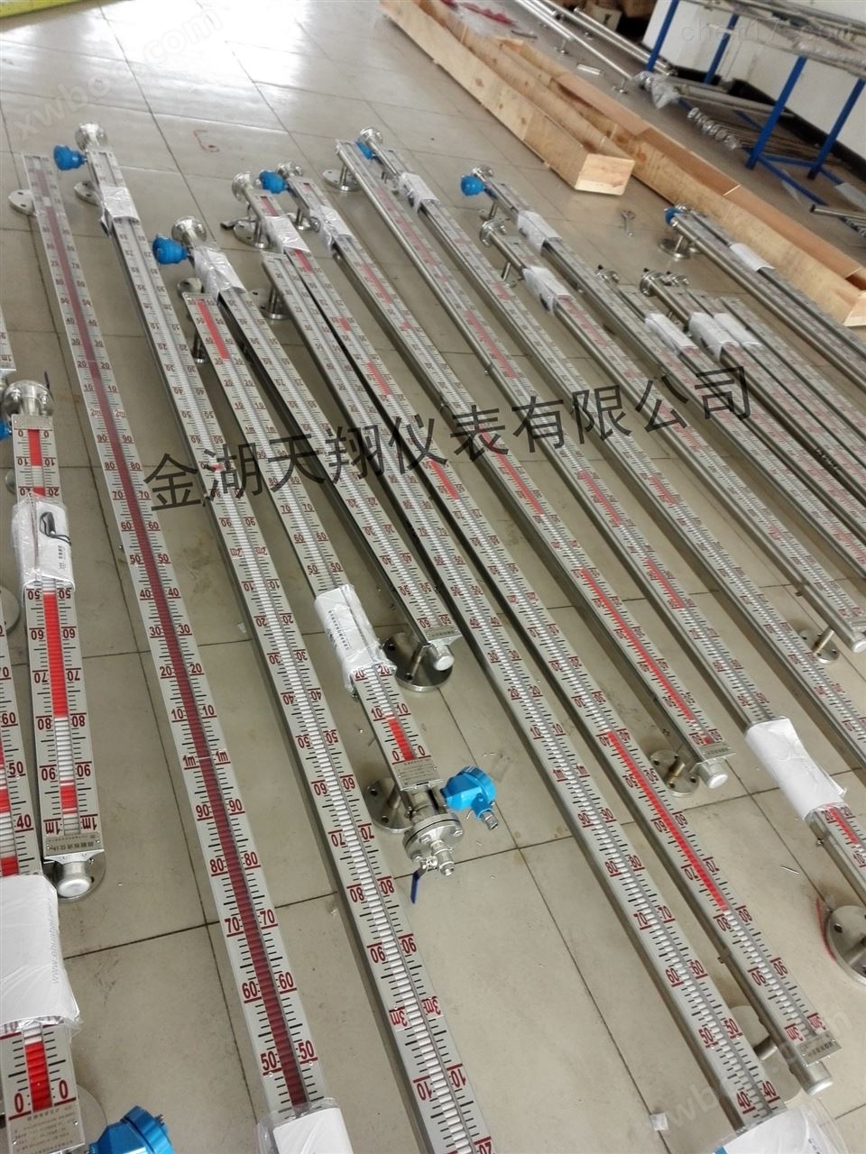
The structural principle of the fuel level gauge is shown in the diagram. The body is a connected pipe body, which is connected to the user container through a flange. There is a magnetic float inside the connected pipe body, which rises and falls with the rise and fall of the liquid level. An indicator composed of a flip column is fixed outside the tube body. The flip column is composed of red and white colors, and it is white before the liquid level rises. When the liquid level rises, the magnetic float follows suit and drives the flip column to rotate through magnetic coupling180The degree, when translated into red, indicates the liquid level. The red and white boundaries represent the height of the liquid level inside the container.
A drain valve can be installed below the magnetic flap level gauge. When needed, the drain valve can be opened to remove dirt. And there is an exhaust bolt above, which can be loosened to remove air when needed.
On one side of the magnetic flap level gauge tube, upper and lower limit alarms can be installed according to user needs. There are two types of alarms:
(1)XGType alarm: The alarm is equipped with a dynamic (normally open) reed switch. When the float in the main tube rises (falls) with the liquid level to the alarm set point, the magnetic steel inside the float will close the reed switch and emit a contact signal. When the float leaves the alarm point with the liquid level rising (falling), the signal at that point will automatically cancel.
(2)XJType alarm: The alarm is equipped with a magnetic coupling driven alarm insideswitchWhen the float crosses the upper and lower limit alarm points, it drives the alarm switch to emit a signal, achieving liquid level alarm or control. The alarm switch has one normally open contact and one normally closed contact. And it has a memory function that does not restore the liquid level and does not eliminate the alarm signal, which is beneficial for the production processsafetyThe operation played a very important role.
On the other side of the magnetic flap level gauge tube, an electric remote transmitter can be installed according to user needs to convert the liquid level height into a standard current signal output,To provide liquid level signal output,For remote transmission of liquid level signals to the secondary systeminstrumentPerform instruction control and detection.


Fuel level gaugeModel
Accuracy of fuel level gauge 1. Magnetic float level gauge (base type)
(1) Appearance and connection form:
(2) Main technical parameters
Measurement medium: liquid
Measurement range: 400mm to 15000mm
Basic measurement error: ± 10mm
Working medium temperature: -50 ℃ to 110 ℃; High temperature range of 50 ℃ to 300 ℃
Working medium pressure: 0.1MPa to 4.0MPa;
Density of working medium: 0.6g/cm3~1.7g/cm3
G Working medium viscosity: ≤ 0.25Pas
H interface flange specification: HG20594-97, see Table 1
(3) Main technical parameters of electric remote transmission transmitter
Measurement range: 400mm to 15000mm
Basic error: ± 10mm for 400mm~1000mm; ± 1% FS for 1000mm~15000mm
Supply power: 24V DC ± 5%
D output signal: (4-20) mA. DC (two-wire system)
Load resistance: 600 Ω
Environmental temperature: -25 ℃ to+60 ℃
G interface thread: M20 × 1.5
H wiring:
Explosion proof grade: d Ⅱ BT4
Explosion proof certificate number: GYB03163
(4) Main technical parameters of the alarm
i) XG type alarm
Output signal: Contact signal
Contact capacity: 24V DC, 0.5A; 220V.AC、0.2A
Basic error: ± 10mm
Environmental temperature: -25 ℃ to+60 ℃
Wiring: see Figure 3
Explosion proof grade: DIIBT4
Explosion proof certificate number: GYB03163
Ii) XJ type alarm
Output signal: one normally open, one normally closed single pole double throw contact signal
Contact capacity: 24V. DC, 0.5A; 220V.AC、≤1.8A
C working life: 105 times
Basic error: ± 10mm
Environmental temperature: -25 ℃ to+60 ℃
F interface thread: M18 × 1.5
G wiring: see Figure 4
Explosion proof grade: d Ⅱ BT4
Explosion proof certificate number: GYB03163
2-jacket insulated magnetic float level gauge
This level gauge is composed of an insulation jacket installed outside the main body of the base type tube. When in use, steam or other heat medium (or water or other condensing agent) is introduced into the jacket tube to prevent condensation and drastic changes of the working medium inside the main body tube, ensuring normal measurement.
(1) Main technical parameters
Form of jacket pipe interface 1, pipe thread G 1/2 2, flange HG20593-97; DN15 and PN 0.6 are shown in Table 1
The remaining parameters are the same as 1
(2) The main technical parameters of the electric remote transmission transmitter are the same as 1
(3) The main technical parameters of the alarm are the same as 1
3 全塑(PVC)磁性浮子式液位计(耐腐型)
(1) Appearance and connection form: see Figure 6
(2) Main technical parameters
Measurement range: 400mm-6000mm
B working medium temperature: -40 ℃ to+60 ℃;
Working medium pressure:<1.25MPa
D interface flange: HG20593-97: DN15, PN1.0 see table, other parameters are the same as 1
(3) The main technical parameters of the electric remote transmission transmitter are the same as 1
(4) The main technical parameters of the alarm are the same as 1
4 Steel plastic composite magnetic float level gauge (strong corrosion resistant type)
(1) Appearance and connection form: see Figure 7
(2) Main technical parameters
Measurement range: 400mm-6000mm
B working medium temperature: -50 ℃ to+200 ℃;
Working medium pressure: 0.1MPa-0.6MPa
D interface flange: HG20594-97: DN25, PN1.0 see Table 1
The remaining parameters are the same as 1
(3) The main technical parameters of the electric remote transmission transmitter are the same as 1
(4) The main technical parameters of the alarm are the same as 1
3 top mounted magnetic float level gauge
(1) Appearance and connection form: see Figure 8
Measurement range: 400mm-6000mm
B working medium temperature: -50 ℃ to+250 ℃;
Working medium pressure: ≤ 1.6Mpa
D interface flange: HG20593-97: DN100, PN1.6 as shown in Table 1
The remaining parameters are the same as 1
(3) The main technical parameters of the electric remote transmission transmitter are the same as 1
(4) The main technical parameters of the alarm are the same as 1
Fuel level gaugeSelection Table
type |
model |
Scope and Application |
Ordinary side mounted type |
TX-UHZ-P |
Ordinary float level gauge is a type of on-site display instrument widely used in petroleum, chemical, power, light industry, environmental protection and other departments to continuously display the liquid level in open or pressure vessels. |
Top mounted type |
TX-UHZ-D |
Suitable for various underground fluid storage tanks, it can display liquid level on the ground. Not suitable for working environments with strong vibrations and strong magnetism (working pressure ≤ 1.6MPa); Measurement range ≤ 2m). |
4-20mA remote transmission type |
TX-UHZ-C |
Suitable for on-site observation that is inconvenient and requires ground observation or even remote transmission output to the control room for observation, sound and light alarms, and control pump shutdown |
Equipped with alarm switch |
TX-UHZ-K |
Equipped with upper and lower limit (high and low position) alarm switches, with switch output, generally used for sound and light alarms or controlling the opening and closing of pump valves. |
corrosion-resistant type |
TX-UHZ-F |
Especially suitable for liquid level measurement indicators with corrosiveness and toxicity (working pressure ≤ 1.6MPa); Measurement range ≤ 2m). |
High temperature type and atmospheric pressure type |
SC-UHZ-T |
Suitable for measuring the liquid level of liquid media in closed containers with temperatures ranging from 150 ℃ to 450 ℃ and process pressures between 0-2.5Mpa (2.5-4MPa belongs to medium pressure). |
High pressure type, room temperature type |
SC-UHZ-Y |
Suitable for measuring the liquid level of liquid media in closed containers with temperatures below 100 ℃ (100-150 ℃ belongs to medium temperature) and process pressures of 4Mpa-10MPa (10-20MPa specially customized). |
High temperature and high pressure type |
TX-UHZ-H |
Suitable for measuring the liquid level of liquid media in closed containers with temperatures above 200 ℃ and process pressures above 10Mpa (below 20Mpa). |
Steam jacket heat tracing |
TX-UHZ-Q |
Suitable for measuring liquid media with high viscosity, high or low temperature (this instrument requires the use of a heat tracing device). It is also a common measure |
Electric heating and heat tracing |
TX-UHZ-V |
The electric heating magnetic flap level gauge is installed with an electric mixing heat source and asbestos insulation layer outside the main body of the base type, which can maintain the temperature of the liquid inside the main body at around 75 ℃, thus allowing the liquid to flow normally |
Vacuum jacket insulation |
TX-UHZ-Z |
It is a rare measure to add a vacuum cylinder outside the main tube of the liquid level gauge to insulate the measured medium from the outside. |
Thermal insulation cotton for antifreeze and insulation |
TX-UHZ-M |
Using insulation cotton for insulation, it is suitable for situations where slight low temperatures require anti freezing insulation. Belonging to common insulation measures |
Explosion-proof type |
TX-UHZ-B |
This instrument is suitable for situations where remote transmission of electrical signals is required in flammable and explosive environments. It comes with electronic devices such as 4mA to 20mA current signals or liquid level transmitters with upper and lower limit alarm settings. |
Fuel level gaugeInstallation method
1: We must first understand the operating environment of our equipment and what the measuring medium is. Even if we do not know what material is needed, our company can determine the material used for the equipment based on the medium.
2: When equipped with remote transmission supporting instruments, the following measures should be taken: the remote transmission supporting instruments should be tightly attached to the main pipe of the liquid level gauge and fixed with stainless steel clamps (iron is prohibited); The sensing surface on the remote transmission supporting instrument should face and be closely attached to the main pipe; The zero position of the remote transmission supporting instrument should be on the same horizontal line as the zero position indication of the liquid level gauge; The connection between remote transmission supporting instruments and display instruments or industrial control computers shall be separately laid through protective pipes or shielded two core cables; After the wiring holes of the junction box are laid, it is required to be well sealed to prevent rainwater, moisture, and other factors from entering and causing the remote transmission supporting instruments to malfunction. The junction box should be promptly covered after maintenance or debugging is completed.
3: According to the condition of the medium, the main pipe should be cleaned irregularly to remove impurities;
4: For exceeding a certain length (ordinary type>3Rice, anti-corrosion type2The liquid level gauge (meter) needs to be reinforced with a middle flange or ear hook as a fixed support to increase strength and overcome its own weight;
5: Installation position: It should avoid or be far away from the inlet and outlet of the material medium to prevent rapid changes in the local area of the material fluid, which may affect the accuracy of liquid level measurement;
6: When debugging, the upper inlet valve should be opened first, and then the lower valve should be slowly opened to allow the medium to enter the main pipe smoothly (during operation, the medium should avoid rapid impact on the float, causing the float to fluctuate dramatically and affecting the display accuracy). Observe whether the magnetic red and white balls flip normally, then close the lower inlet valve, open the drain valve, and let the liquid level in the main pipe decrease. Follow this method three times, if it is normal, it can be put into operation (except for corrosive and other special liquids); There are also other names on the market, such as magnetic flap level gauge, magnetic flap column level gauge, etc. But the parameters they need to know for ordering are certain, such as the anti-corrosion material required for corrosive media, and the anti-corrosion level varies equally according to the corrosiveness level of the media.
installation diagram 
Precautions
1.For those exceeding a certain length (ordinary type)>3Rice, anti-corrosion type>2Meter level gauge.
2.The installation position should avoid or be far away from the inlet and outlet of the material medium to prevent rapid changes in the local area of the material fluid, which may affect the accuracy of liquid level measurement;
3.When equipped with remote transmission instruments, the following measures should be taken:
4.The remote transmission supporting instruments should be tightly attached to the main pipe of the liquid level gauge and fixed with stainless steel clamps (iron is prohibited);
5.The sensing surface on the remote transmission supporting instrument should face and be closely attached to the main pipe;
6.When debugging, the upper inlet valve should be opened first, and then the lower valve should be slowly opened to allow the medium to enter the main pipe smoothly (during operation, the medium should avoid rapid impact on the float, causing the float to fluctuate dramatically and affecting the display accuracy). Observe whether the magnetic red and white balls flip normally, then close the lower inlet valve, open the drain valve, and let the liquid level in the main pipe decrease. Follow this method three times, if it is normal, it can be put into operation (except for corrosive and other special liquids);
7.The main tube should be periodically cleaned to remove impurities based on the condition of the medium.