-
E-mail
1810392383@qq.com
-
Phone
18962431158
-
Address
No. 168 Yucheng North Road, Yushan Town, Kunshan City
Product Categories
Kunshan Aobo Testing Instrument Co., Ltd
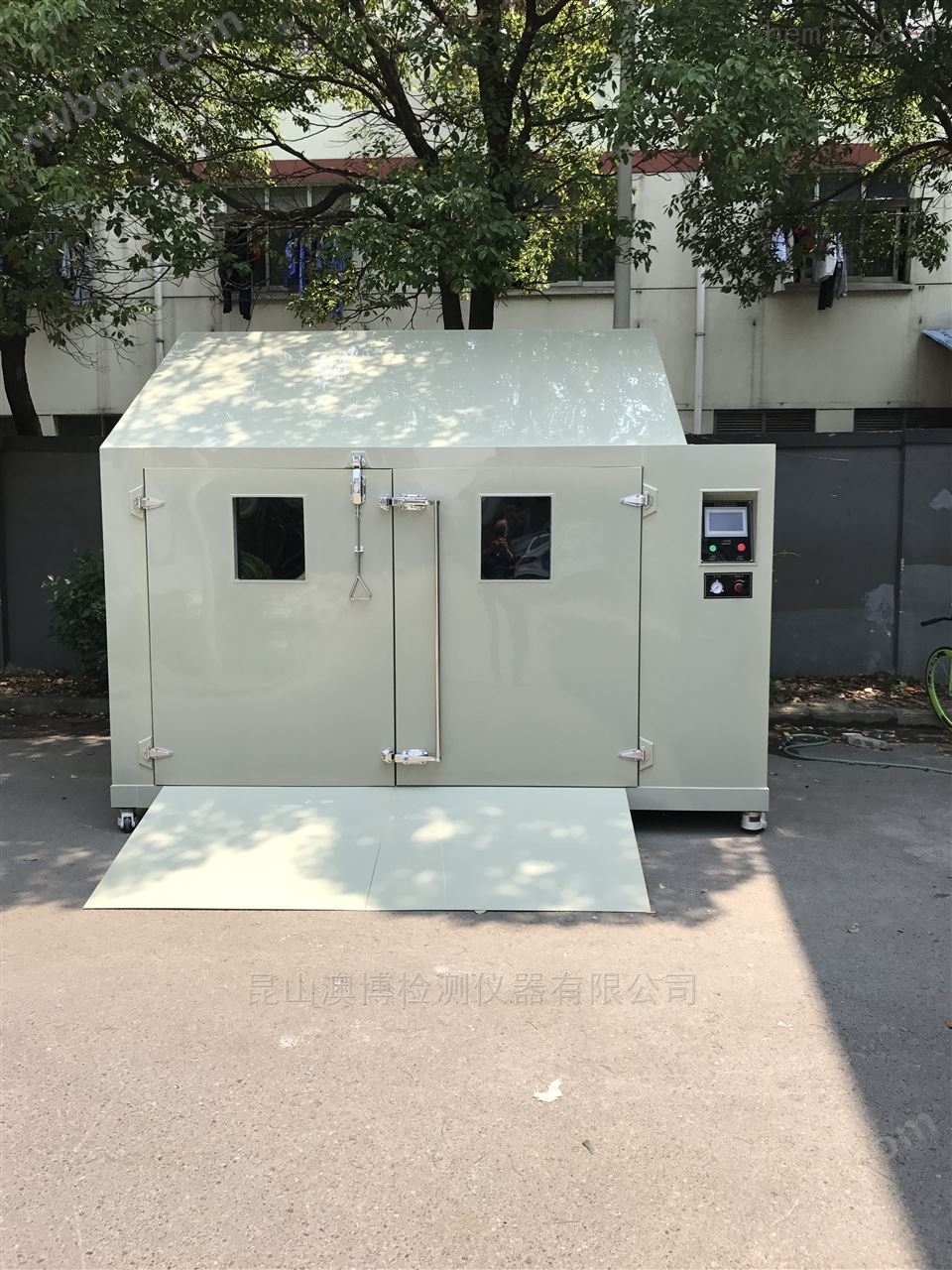
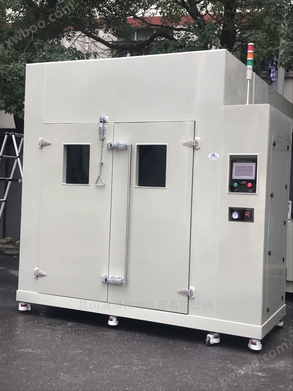


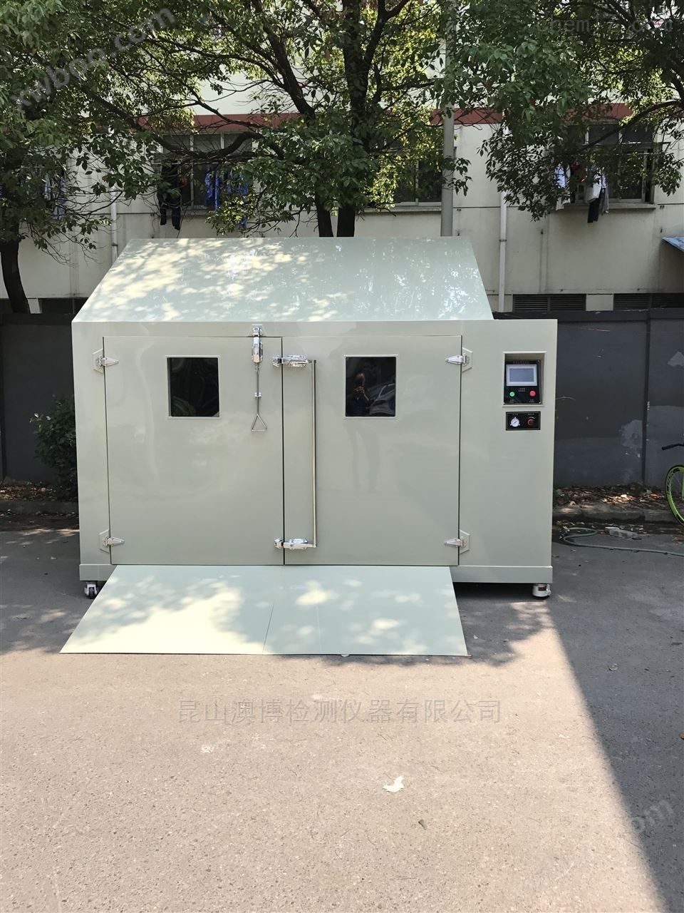
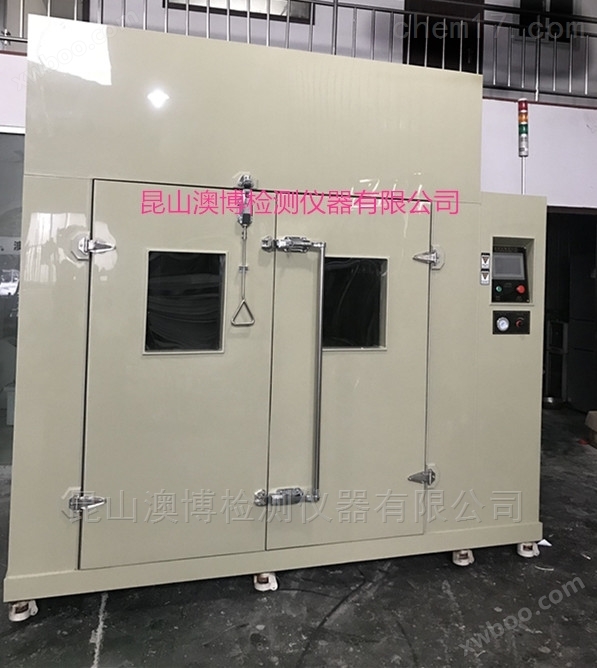
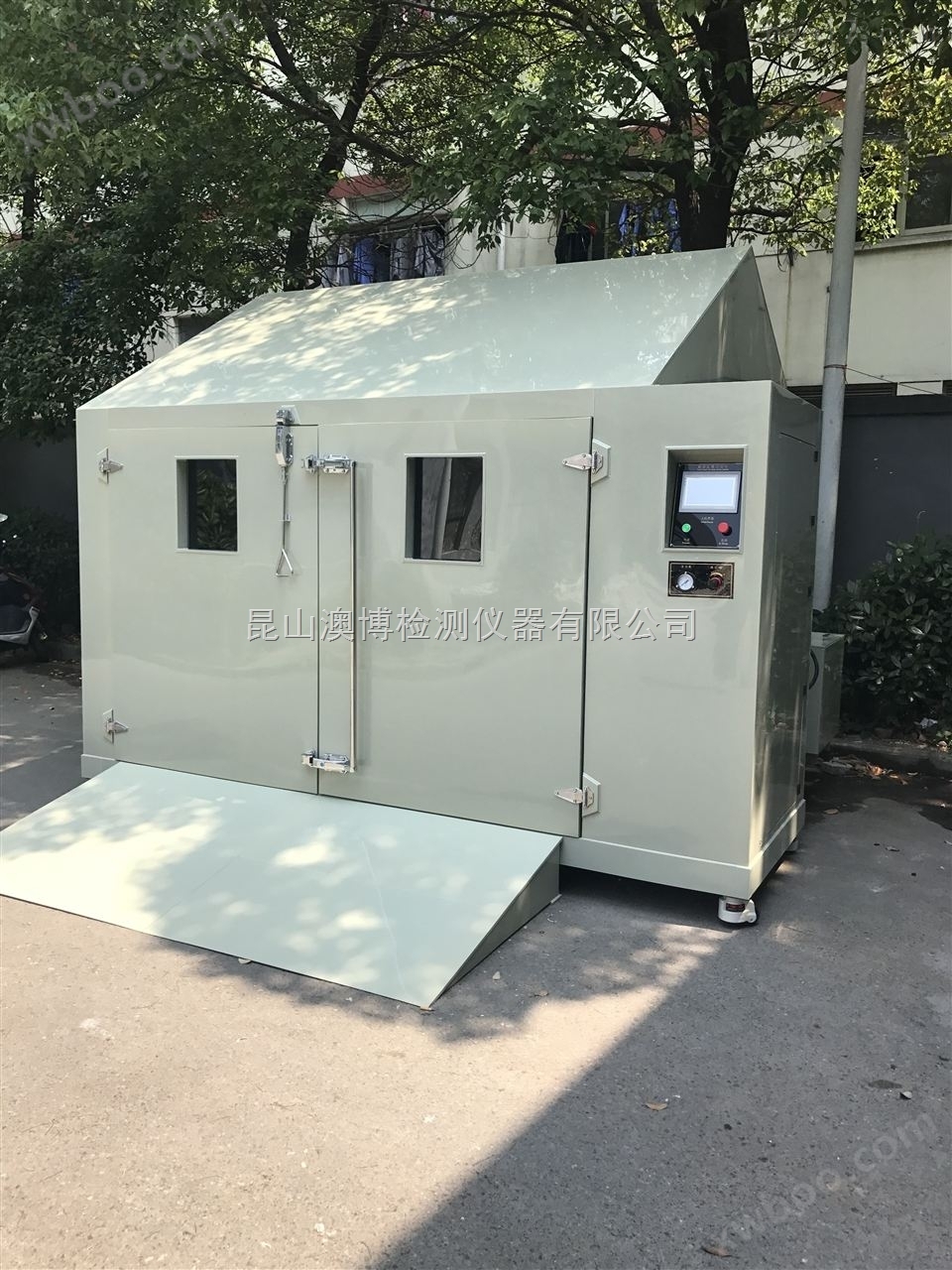
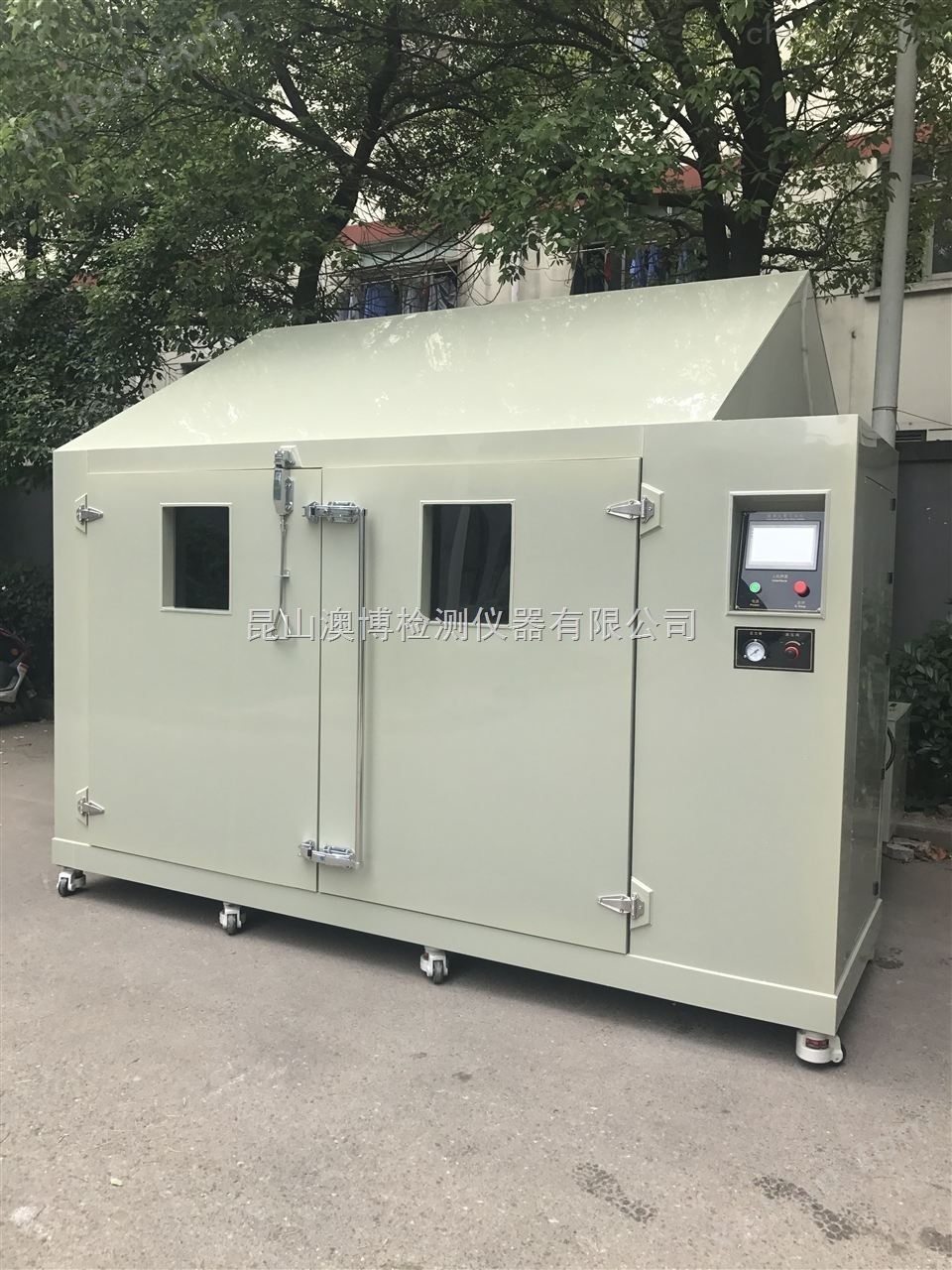
Large walk-in salt spray laboratory
NegotiableUpdate on 01/22
- Model
- Nature of the Manufacturer
- Producers
- Product Category
- Place of Origin
Overview
The salt spray chamber can simulate typical environmental conditions in nature at any time without being limited by time and season. Putting the product into an environmental simulation laboratory for environmental simulation testing, replacing the usage environment with a simulated environment, can save a lot of manpower and material resources, and save development costs. At the same time, environmental simulation testing is based on the product's usage environment conditions, controlling the product's usage conditions. The test has an "acceleration" property, which can shorten the product's testing cycle
Product Details
Large walk-in salt spray laboratoryexecution standard
1.1GB/T10587-2006Technical conditions for salt spray test chamber
1.2GJB150.11A-2009Environmental testing methods for military equipment laboratories - Part 11: salt spray test
1.3GB/T2423.17-2008Basic Environmental Testing Regulations for Electrical and Electronic Products experimentKaSalt spray test method
1.4GB/T10125-1997Artificial atmosphere corrosion test salt spray test
Step in salt spray laboratory testCollection standard:
GB/T5170.8-2008Basic parameter calibration method for environmental testing equipment of electrical and electronic products Salt spray testing equipment
Large walk-in salt spray laboratoryMain parameter indicators
1.Model:AB-300
2.Studio size: 3000 mm×2000 mm×1800mm(Width x Depth x Height) (excluding spire)
Outer box size: 3500mm×2550mm×2300mm(Width x Depth x Height)
3. door : 1600mm×1800mm(height and width)(PPBoard door with double-layer silicone rubber seal and door lock.
4.Temperature range: 35℃-50℃
5.Temperature fluctuation: ±0.5℃(When unloaded)
6.Temperature deviation degree: ±2℃ (When unloaded)
7.Wen degree ladder Degree: ≤2℃
8.Salt spray sedimentation rate: 1-5 ml/h/80cm2adjustable
9.Salt water concentration: 0.5 ~5%adjustable
10.Test time: 0~999 HTheMTheS;How to translate
11.Observation window: 350×450mm(Length x Height)
12.Spray mode: airflow spray, continuous/The gap is arbitrary.
13.Bottom load-bearing capacity: ≥400kg
15.Average working hours:>2000h
16.Average lifespan:>10 years
17.Noise: ≤ 75dB
18.Rated voltage of laboratory:AC(380±38)V 50Hz±0.5Hz
2、 Working principle of walk-in salt spray laboratory:
1.Working Principle Diagram(See attached image)
3、 Composition of walk-in salt spray laboratory:
1.Laboratory body
2.Gas supply system
3.Saltwater supply system
4.Spray system
5.Drainage, sewage, pressure balance system:
6.Quick Mist Exhaust Device
7.Electrical control system
8.water treatment system
1.Laboratory body
1.1Composed of modular assembled storage panels, it directly forms a sealed test space. The box can automatically maintain insulation within the specified temperature range, while also meeting the requirements for the layout of the fogging device, air circuit, saltwater supply pipeline, and temperature sensor opening placement. Due to the high temperature during the salt spray test(35~50℃)Moreover, it has strong corrosiveness, so the material used to manufacture the salt spray test box body should have certain anti-corrosion and temperature resistance properties. At present, most of the box materials are made of plastic, fiberglass, and stainless steel. Fiberglass andPVCCorrosion resistance is good, and special stainless steel materials should also be selected. General stainless steel is not salt resistant. In order to achieve the requirements of corrosion resistance, easy cleaning, temperature resistance, and certain strength, the internal bile material of this chamber is made of12mmofPPBoard; The outer wall material isPPPlate, reinforced with square steel in the middle.
The material combination of the outer wall and the inner liner is as follows:
Externally for8mmthickPPBoard, inside is12mmthickPPboard
1.2The salt spray test stipulates that the water droplets formed by spray shall not fall on the test piece, and the included angle of the top of the laboratory shall have a certain angle, generally110ºThus, the formed droplets flow along the apex to both sides of the laboratory.
1.3The front door is one of the key components of the room. It can meet the requirements of convenient entry and exit of sample vehicles, good insulation, no cold running or condensation around, and lightweight switches. The fourth is good sealing and no salt spray leakage.
1.4Bottom: Adopting12mmthickPPThe plate is reinforced with a channel steel type bottom plate, with an iron plate added in the middle to ensure the overall compressive strength and wear resistance of the bottom surface. The ground is inclined from the outside to the inside towards the collection tank at a certain degree, so that the atomized water can be discharged as soon as possible.
2.Gas supply system
2.1Air flow spray is adopted in this laboratory, so air supply system is required. The function of the gas supply system is to continuously supply fresh, clean, and humid hot air with pressure required for the salt spray test chamber. Our laboratory uses a domestically produced piston compressor as the gas supply source. The ambient atmosphere is compressed into high-pressure air by the air compressor and then enters the gas storage tank, which is connected to the location through the gas pipeline.
2.2In order to ensure that the air entering the nozzle is clean and humid hot air, the gas generated by the air compressor needs to be separated into oil and water. The oil-water separation filter adopts a three-stage filtration method of pre filtration, fine filtration, and oil removal filtration. The filter element made of polymer compound material effectively removes oil, water, and particles from the compressed air. Place it in the position before entering the saturator, striving to achieve maximum ability to remove oil stains.
| parameter
model | handling capacitym3/min | rated work pressureMPa | tall work pressureMPa | particle size um | Residual oil quantity mg/ m3 | interface dimensions | weight K g | |
| LJ33-2F | 2.0 | 0.8 | 1.0 | ≤5 | ≤1 | G3/4 | 30 |
All high-efficiency precision filters are produced using foreign technology structures, and their high-quality filter elements can meet various requirements such as oil removal, water removal, dust removal, and sterilization. The technical parameters of the filter element are as follows:
| Filter level | particle size(um) | dust removal efficiency% | Export residual oil volume(ppm) | initial pressure differenceMPa | service lifeh |
| pre-filteringV | 3 | 100 |
| 0.003 | ≥4000 |
| fine filtrationZ | 0.3 | 99.97 | 0.1(0.8) | 0.005 | ≥4000 |
| Oil removal filtrationA |
| 99.9999 | 0.003(0.0024) | 0.010 | ≥4000 |
2.3Because the spray pressure only needs0.07~0.14MpaThe filtered air needs to undergo secondary pressure reduction, and the * level will reduce the air to0.2~0.3 MPaThe second level is adjusted according to the size of the fog0.07~0.14MPaSo that the spray pressure sprayed from the nozzle is within the specified range.
2.4The salt spray test stipulates that the air entering the laboratory must have a certain temperature and humidity, so a heating and humidification device, namely an air saturator, is added before the compressed air enters the chamber. The temperature value of the saturator is controlled by the main control board, and the spray pressure and temperature are adjusted according to different ambient temperatures and test temperatures. The saturator is a pressure vessel with a pressure resistance of ≥6KgMade of stainless steel, the saturator is filled with deionized water and heated with an electric heating tube. Equipped with water level gauge, inlet valve, exhaust valve, drain valve, sensor testing hole, etc. One end of the three-way connector is connected to the pipeline leading to the nozzle, and the other end is connected to a pressure gauge. Compressed air enters the saturator and is then passed through ionized water or distilled water for further filtration. Then mix it with the water vapor generated by deionized water or distilled water inside the cylinder, so that the air entering the nozzle is close to the test temperature inside the box, clean and humid.
The pipeline material of the gas supply system is pressure resistantPUManage. All pipes exposed to the air and pipes buried in the outer framework need to be insulated with different insulation materials.
2.5Replenishment of water in the saturator: since the air flowing out of the saturator is humid and hot, it will take away some of the water vapor. Long time operation will continuously consume water, so it is necessary to make up water regularly. In addition, since there is pressure in the saturator under the spray state, and water cannot enter, the air supply must be temporarily stopped, and the water inflow is also very slow. In this case, it is necessary to set two solenoid valves on the saturator. One of them is the inlet solenoid valve, and the other is the outlet (ventilation) solenoid valve. When water enters, both solenoid valves open simultaneously. You can also manually add water.
3.Saltwater supply system:
3.1The air flow spray shall be carried out continuously, and the continuous automatic supply of brine is *. The brine supply system is set up to achieve this purpose. The brine tank is usually placed on the upper part of the room. If proper control is not carried out, either the brine will flow out quickly or the demand for spray will not be met.
3.2In order to maintain a certain siphon height, it is necessary to keep the saltwater siphon level at200~500mmWithin the scope. The pre configured salt solution is stored in a plastic container and pumped into the salt water supply container by a magnetic pump. The salt water supply container is arranged on the outer frame and is controlled by an automatic liquid level controller to operate the magnetic pump. Maintain the upper and lower limits of the water level at10mmWithin.
4.Spray system:
4.1The function of the spray device is to use the high pressure air supplied by the air source system to inject the salt water from the nozzle at high speed. The salt water is sucked up by the siphon principle and mixed with the air to produce a misty mist. Because the fog contains some unmeasured water droplets, the sprayed misty air flow cannot be directly introduced into the test chamber. Instead, it should be hit on a salt spray baffle first to break the unmeasured water droplets into fog or block the redundant salt fog back, so that the sprayed fog is really a fine fog without water droplets. The magnitude of salt spray deposition is directly related to the pressure of saltwater supply and gas supply, as well as the angle of the baffle.
4.2Refractive typeThe baffle of is placed in front of the salt spray nozzle, which is different from the reflective type, and faces the test space. It uses the lifting angle of the baffle to lift the physical airflow to the top of the salt spray test chamber and then settle freely (industry name: baffle type spray). This laboratory adopts a Japanese non crystalline nozzle structure with baffle atomization. Based on our experience, a portion of the atomized baffle will not atomize and will flow down, resulting in a waste of saltwater resources. Therefore, a collection device can be added to collect the flowing saltwater, thereby maximizing the utilization of saltwater resources. Our room requires an appointment3Regarding the nozzle. The nozzle is made of resin glass and equipped with a runoff regulation system. They are installed on brackets and can be200mmVertical movement within the range, and can rotate up, down, left, right, with an angle of ±90°Angle, continuously adjustable.
5.Drainage, sewage, pressure balance system:
5.1In the process of spray, most of the salt solution falls into the chamber except for a part taken away by the mist exhaust system. The drainage pipe and fog pipe can be organically combined to discharge both salt spray and accumulated water through a channel, while maintaining pressure balance. The final fog outlet should be far away from the laboratory. If it is necessary to treat the discharged salt spray, an air purification tower can be used for treatment.
6.Quick Mist Exhaust Device:
6.1After the experiment, there is still a large amount of salt spray inside the chamber, which cannot settle or be discharged outside in a short period of time. In order to facilitate the early entry of test personnel into the chamber, our laboratory is designed with a set of rapid mist exhaust devices with pressure balance windows.in5The indoor salt spray can be eliminated within about minutes.
7.electric control system
7.1Laboratory control system
The human-machine interface of this control system,Adopting Advantech embedded touch screen, the main controller adopts Songhua programmable controller. The control system is specially customized by our company for customers to meet different testing modes. The system control is precise, smooth, and does not drift. The control interface adopts a bilingual operation interface in Chinese and English, with detailed experimental parameters and simple and fast settings. The experimental information is complete and has detailed alarm indication functions.
8.water treatment system
This deionized water generator is composed of a cation anion exchanger and reverse osmosis. Ion exchange is a technology for removing ionic substances from water. The ion exchange method can be used to produce soft water, pure water, and ultrapure water. The reverse osmosis system adopts a single-stage and multi-stage multi-stage design based on the actual situation of the user. The combination of reverse osmosis and ion exchange equipment can greatly extend the regeneration cycle of resin, not only improving the purity of water, but also making it easier to produce1MΩ~18 MΩ.cmHigh purity water to meet the needs of different users. The purified water obtained by using an ion exchanger is more cost-effective and efficient than water obtained by distillation.
4、 Walk in salt spray laboratory safety protection system
1.overtemperature protection
2.overvoltage protection
3.Heating tube malfunction alarm
4.Water shortage alarm
5.Power failure alarm
6.Door closed status display
5、 After sales and accompanying accessories of the equipment
1Spare parts, tools, and technical documentation
(1) The seller shall provide the necessary spare parts (vulnerable parts) during the warranty period to ensure the safe, stable, and reliable operation of the equipment.
(2) The seller provides random tools.
(3) The seller shall provide operation manuals, structural diagrams, electrical schematics, heating system principles and structural diagrams, electrical and mechanical interface parameters, as well as other relevant information required by the buyer for the correct use and maintenance of the equipment.
2Installation, debugging, and acceptance(1) This equipment is installed and debugged by the seller, and will be delivered to the buyer's project site within 10 days after the buyer notifies the sellerWithin the day, the seller is responsible for installation and debugging, which meets the buyer's normal usage requirements.
(2) Pre acceptance location: Supplier
(3)Delivery time: 60 days (from the date of receipt of the advance payment)
(4) Conduct formal acceptance at the buyer's project site.
3After sales service
(1) The seller is responsible for providing free technical training to the buyer's operators and maintenance personnel. The general number of trainees is 2-3 people, starting from equipment debugging until the trainees are present.
(2) The whole machine comes with a one-year warranty and lifetime maintenance.
(3) Under the condition that the purchaser complies with the storage, use, and installation rules, if the equipment cannot operate normally due to quality problems within one year from the date of acceptance, the supplier shall send personnel to provide free on-site service and repair within 48 hours after receiving the notice. After the warranty period, the supplier shall give priority to solving the quality problems of the equipment and charge material fees at its discretion.
Similar Product Recommend