-
E-mail
750556873@qq.com
-
Phone
13838265705
-
Address
11A-1-385, South China City, Longhu Town, Zhengzhou City
Product Categories
Henan Shangzhou Valve Co., Ltd
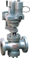

Water supply rotary control valve
NegotiableUpdate on 01/21
- Model
- Nature of the Manufacturer
- Producers
- Product Category
- Place of Origin
Overview
The product description of the water supply rotary control valve mainly consists of valve body, sleeve, valve disc, valve stem and other parts. There are throttling holes on both the sleeve and valve disc. By rotating the valve disc inside the valve seat to change the flow area, it is suitable for medium and low-pressure boiler feedwater pipelines and high-pressure heater drain pipes. By rotating the cylindrical valve disc to change the window area formed with the valve seat, the purpose of regulating flow can be achieved. The rotation opening and closing angle of the regulating valve is 60 degrees, indicated by the opening indicator plate above the regulating valve. Can be equipped with an electric actuator for remote automation operation.
Product Details
Welding rotary control valve T60HProduct Description
The rotary control valve is mainly composed of valve body, sleeve, valve disc, valve stem and other parts. There are throttling holes on both the sleeve and valve disc. By rotating the valve disc inside the valve seat, the flow area can be changed and the flow rate can be adjusted. The valve cover is equipped with an opening indicator ruler to display the opening status of the valve. Installed on oil, water and other pipelines, the size of the window area formed by the valve disc and the valve seat is changed by rotating the cylindrical valve disc, thereby achieving the purpose of regulating the flow rate. The opening and closing angle of the regulating valve is 60 degrees. It is indicated by the opening indicator plate installed above the regulating valve. Suitable for media on water pipelines, installed on low, secondary, and high-pressure boiler feedwater or high-pressure boiler drain pipelines. The feedwater regulating valve is installed on the boiler feedwater pipe to regulate the feedwater flow rate to meet the needs of boiler and load operation.Water supply rotary control valveSuitable for water supply pipelines of medium and low pressure boilers and drain pipes of high pressure heaters, by rotating the cylindrical valve disc to change the window area formed with the valve seat, the purpose of regulating flow can be achieved. The rotation opening and closing angle of the regulating valve is 60 degrees, indicated by the opening indicator plate above the regulating valve. Can be equipped with an electric actuator for remote automation operation.

Water supply rotary control valveInstallation and usage precautions:
The factory installation must be properly handled after receiving the regulating valve from the site. Operators need to adjust the regulating valve at various stages of installation, and careless handling of the regulating valve may cause significant delays in the operation of the device. Suggest considering the following specific requirements:
(1) The air source used to operate pneumatic control valves should be oil-free and dry, especially for valves with positioners.
(2) The inlet piping of a small diameter regulating valve should be equipped with a suitable filter to filter out impurities from the piping system and avoid damaging the valve.
(3) When installing valves in the system, the valve body should avoid excessive pressure, which is particularly important for valve body separation valves.
(4) Before the initial commencement and after the shutdown for maintenance, the filter screen shall be installed in front of the regulating valve to filter out the scale, rust and other sundries in the pipeline. Whenever possible, a short pipe joint should be installed in the piping system, and the piping system should be flushed before installing the regulating valve.
(5) For regulating valves operated in dusty environments, a rubber or plastic cover should be installed around the valve stem to protect the polished surface of the valve stem from damage.
(6) It is essential to follow all instructions provided by the manufacturer regarding the switch positions for adjustments and auxiliary equipment. For example, do not forget the bypass switch at the bypass position of the valve positioner
(4) It can be imagined that even with good design, high-pressure fluid will inevitably accumulate when cutting off. Therefore, it is recommended to install vent valves and/or discharge valves on each side of the regulating valve if the potential energy of the accumulated liquid is highly dangerous.
(5) For valves that accumulate a large amount of high-pressure materials, it is necessary to consider installing two vent valves and a discharge valve. Only a small amount of material accumulates between two valves, while gradually releasing the system pressure, allowing the pressure to repeatedly accumulate and discharge between these two discharge or vent valves. Note that the regulating valve must be open during this process.
(6) If the discharged fluid is a hazardous gas, the venting pipeline must be connected to a safe location.
(7) If the regulating valve needs to be removed from the system after installation, the shut-off valve should be closed and marked. If there are hazardous fluids or pollutants in the regulating valve, corresponding markings should be added for proper cleaning before disassembling the valve.
(8) Be sure to install the regulating valve according to the arrow in the flow direction. If the orientation indicated by the valve arrow provided by the manufacturer is incorrect, this situation should be reported.
(9) Before installation, it is necessary to refer to the specific instructions provided by each valve manufacturer

Working principle and structural description
1、 Mainly composed of valve body, valve seat, valve disc, valve stem, valve cover, indicator plate, etc.
2、 The flow regulation of the valve is achieved by the relative rotation of the cylindrical valve disc and seat to change the window area on the valve disc.
3、 The opening and closing range of the valve. The switch range indicated by the opening indicator board above the valve is the same as the switch range of the valve *.
4、 The rotary control valve is operated through a remote controller with a rotary angle of 60 ℃.

Welding rotary control valve T60HMain technical parameters and performance indicators
| Nominal pressure (Mpa) | 1.6 | 2.5 | 4.0 | 6.4 | 10.0 | 16.0 |
| Shell test pressure (Mpa) | 2.4 | 3.75 | 6.0 | 9.6 | 15.0 | 24 |
| Zui High Import Pressure (Mpa) | 1.6 | 2.5 | 4.0 | 6.4 | 10.0 | 16.0 |
| flow characteristics | Linear or equal percentage | |||||
| leakage | GB10869-1989 (Grade I) | |||||
Welding rotary control valve T60H main materials
| Part Name | Part material |
| valve body | WCB |
| Valve cover bottom cover | WCB |
| valve seat | 2Cr13 |
| valve disc | 2Cr13 |
| valve stem | 2Cr13 |
| filler | flexible graphite |
Flow coefficient of welding rotary control valve
| DN | 15 | 20 | 25 | 32 | 40 | 50 | 65 | 80 | 100 | 125 | 150 | 200 | 250 | 300 | 350 | 400 | 500 |
| Cv | 2 | 4 | 4.5 | 5 | 14 | 15 | 16.5 | 51 | 52 | 80 | 105 | 150 | 225 | 360 | 480 | 630 | 800 |

| Nominal diameter DN | Overall dimensions | ||||
| L | L1 | H | H1 | ||
| 1.6/2.5MPa | 4.0MPa | ||||
| 15 | 160 | 180 | 155 | 170 | 95 |
| 20 | 160 | 180 | 180 | 175 | 98 |
| 25 | 180 | 200 | 180 | 175 | 110 |
| 32 | 200 | 220 | 180 | 175 | 110 |
| 40 | 220 | 240 | 195 | 190 | 125 |
| 50 | 250 | 270 | 195 | 190 | 125 |
| 65 | 280 | 300 | 195 | 190 | 130 |
| 80 | 310 | 330 | 245 | 245 | 160 |
| 100 | 350 | 380 | 245 | 245 | 170 |
| 125 | 400 | 450 | 350 | 300 | 200 |
| 150 | 450 | 500 | 350 | 310 | 210 |
| 200 | 500 | 550 | 500 | 345 | 240 |
| 250 | 650 | 580 | 395 | 290 | |
| 300 | 800 | 750 | 470 | 335 | |
| 350 | 850 | 750 | 520 | 375 | |
| 400 | 900 | 750 | 560 | 405 | |
| 500 | 950 | 800 | 650 | 465 |
|