-
E-mail
149645389@163.com
-
Phone
13971209917
-
Address
Wuhan Donghu Development Zone Optics Valley Avenue 303 Optics Valley Chip Center Pilot Industrial Park
Product Categories
Hubei Pilot High Test Electrical Holdings Co., Ltd
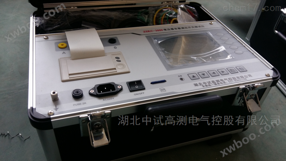
Three phase capacitance and inductance tester for testing primary reactors
NegotiableUpdate on 01/22
- Model
- Nature of the Manufacturer
- Producers
- Product Category
- Place of Origin
Overview
1、 Product Overview: Reactive power compensation capacitors are important equipment for achieving reactive power balance in power systems. In recent years, reactive power issues have received widespread attention from the power sector, and complete sets of reactive power compensation devices have been widely deployed in distribution networks. The power supply requires real-time balance between active and reactive power in the system. Therefore, reactive power compensation devices should meet the requirements of automatic tracking and real-time compensation, which inevitably requires frequent switching of reactive power
Product Details

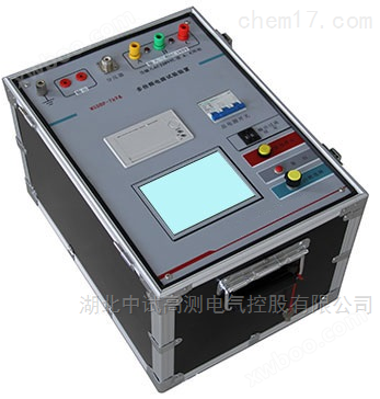
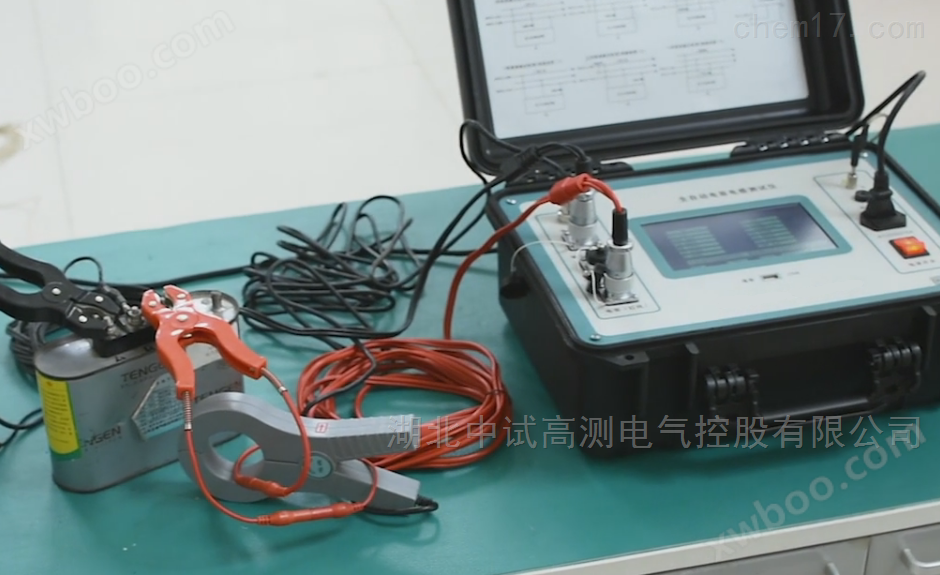
Structural characteristics of fully automatic single-phase capacitance and inductance tester:
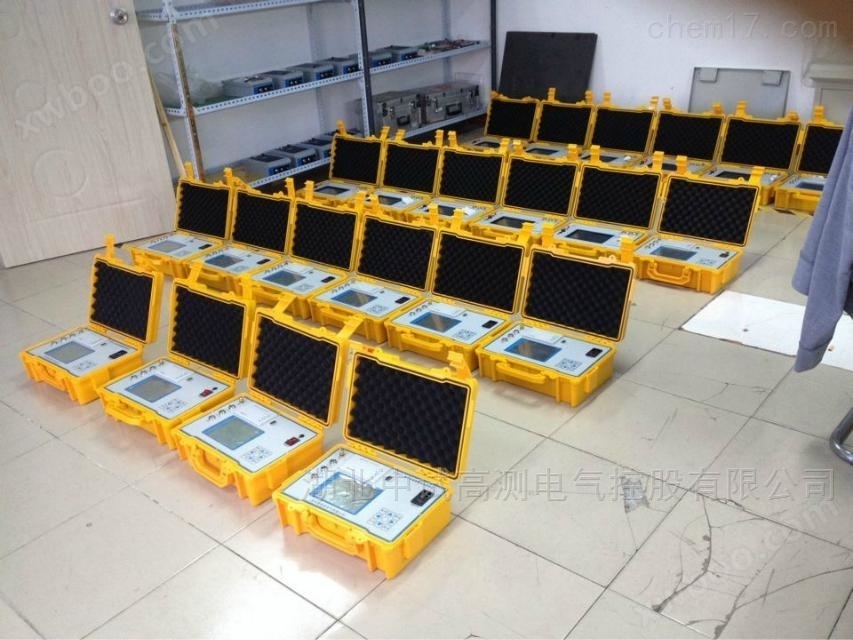
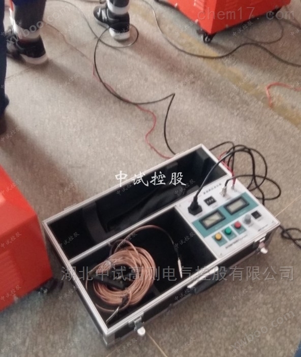
This product consists of two parts: the main unit and the accessory box. The main unit is the core of the instrument, and all electrical parts are installed inside the main unit. The main unit outer box adopts a high-strength imported waterproof injection molded chassis, which is sturdy and durable. The accessory box is used to place test wires and supporting tools.
Technical specifications of fully automatic single-phase capacitance and inductance tester:
Output voltage: 0-20V, automatically adjustable
Measurement range: capacitance: 0.01uF -4000uF
Inductance: 1mH-20H
Resistance: 50m Ω -20k Ω
Current: 50mA-10A
Voltage: 0-20V
Capacity range: 0-20000 kvar
Measurement accuracy: capacitance: ± (1%+2 words)
Inductance: ± (1%+2 words)
Current: ± (0.5%+2 characters)
Voltage: ± (0.5%+2 characters)
Capacity: ± (1%+2 words)
Resolution: Voltage: 0.1mV
Current: 0.1mA
Capacitor: 0.1nF
Inductance: 0 1mH
Dimensions: 320 × 240 × 130mm3
Instrument weight 4kg
Working temperature: -15 ℃~+45 ℃
Charging power supply: AC 160V~260V
Edge: ⑴ The edge resistance between the voltage and current input terminals and the casing is ≥ 100M Ω.
⑵ The working power input terminal is subjected to a power frequency of 2kV (effective value) between the casing for a 1-minute experiment.
Notes:
1. During the measurement process, be sure not to touch the metal parts of the test line to avoid being damaged by electrical shock.
2. When measuring wiring, it is necessary to strictly follow the instructions, otherwise the consequences will be borne by oneself.
Before testing, it is necessary to carefully check whether the set parameters are correct.
4. Use a grounded power socket.
When conducting a capacitance test on the III, the short-circuit effect must be good, otherwise it will affect the test results.
6. The test wiring work must be carried out with the tested circuit grounded to prevent induced voltage electric shock. All short circuits, grounding, and leads should have sufficient cross-sectional area and must be securely connected. The testing organization work should be rigorous and communication should be smooth to ensure the safe and smooth progress of the testing work.
When the instrument needs to be charged, turn off the working power (press "O" to turn off), plug in the power cord, and the yellow light of the charging indicator will start flashing, indicating that the charging has entered a normal state.
Similar Product Recommend