-
E-mail
149645389@163.com
-
Phone
13971209917
-
Address
Wuhan Donghu Development Zone Optics Valley Avenue 303 Optics Valley Chip Center Pilot Industrial Park
Product Categories
Hubei Pilot High Test Electrical Holdings Co., Ltd
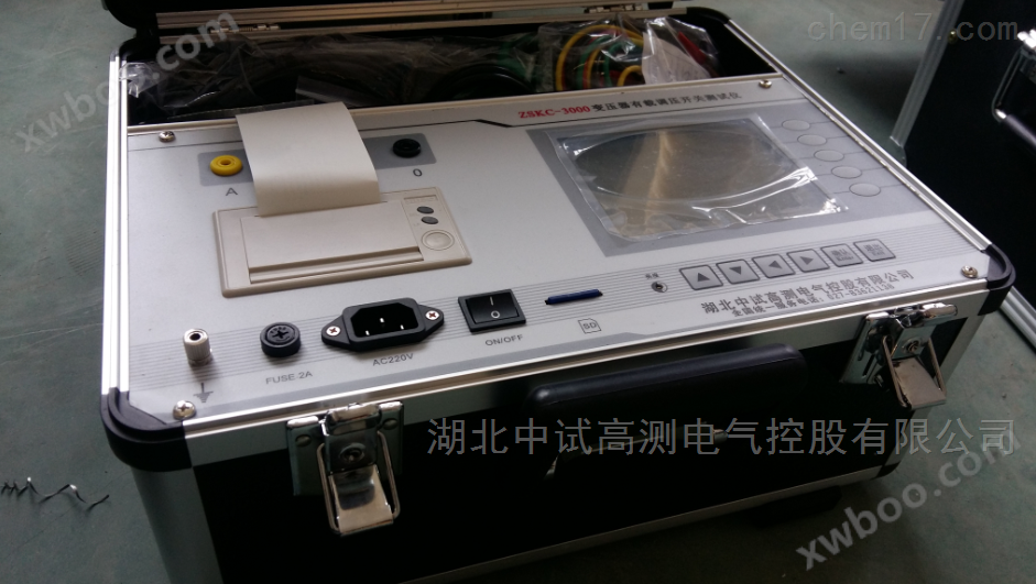
Method for live testing of three-phase capacitance with inductance tester
NegotiableUpdate on 01/22
- Model
- Nature of the Manufacturer
- Producers
- Product Category
- Place of Origin
Overview
1、 Please read the instruction manual carefully before testing the product overview; To ensure accurate testing, please demagnetize the power transformer or conduct a DC resistance test before using this instrument. The transformer on load tap changer characteristic tester is a comprehensive measuring instrument used to measure and analyze the electrical performance indicators of power transformers and special transformer on load tap changers in power systems. It is computer-controlled and connected to
Product Details
Hubei Zhongce Gaoce Electrical Holdings Co., Ltd. answers your question: Method for live testing of three-phase capacitance with variable frequency three-phase capacitance and inductance tester
Variable frequency three-phase capacitance and inductance tester for three-phase capacitance testing
1. Three phase capacitor parameter setting
After selecting the "Three phase Capacitor" item under the "Main Menu" screen, press the "Confirm" button to enter the "Three phase Capacitor Parameter Settings" screen, as shown in Figure 6.
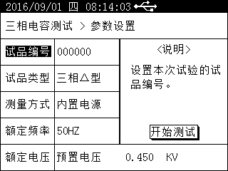
Figure 6
Please refer to section 5.3.1 for specific usage instructions.
Sample type: High and low voltage parallel capacitor banks for power, with internal connection methods including three-phase Y-shape, three-phase Yn shape, three-phase △ shape, and three-phase III shape. This instrument is pre-set with all connection types. Please select the correct sample type for different connection methods and correctly connect the test lines.
Measurement method: When conducting three-phase capacitance testing, only the built-in power supply of the instrument can be used for testing, and external power supply cannot be used.
2 Three phase capacitance test
After completing the parameter settings, connect the test line as required to start the test. After the test is completed, enter the "Test Results" screen, as shown in Figure 7, where you can perform operations such as "Store Data", "Print Data", and "Continue Test".
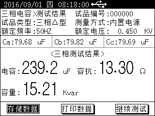 Figure 7
① Phase capacitance display, showing single-phase capacitance of phase A, phase B, and phase C.
② Three phase total capacitance display, displaying the capacitance, reactance value, and capacity value of the three-phase total capacitance.
Three phase capacitor test wiring
When testing three-phase capacitance, simply insert the testing wire that comes with the instrument into the instrument, clamp the test sample with voltage clamps according to the wiring requirements, and set the relevant parameters to conduct the test, without the need for an external clamp current transformer.
Three phase Y-shaped
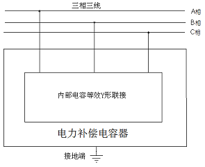
Figure 8
Three phase Yn type
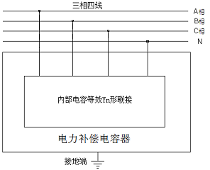
Figure 9
Three phase △ type
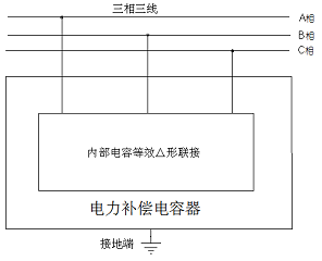
Figure 10
Three phase III type
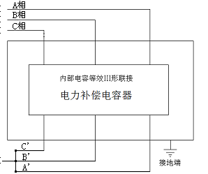
Figure 11
Testing precautions
During on-site testing, it is necessary to ensure that the instrument is reliably grounded.
For the Yn type neutral point grounded test sample, clamp the black clip to the grounding point N.
During on-site testing, the measurement can only be started after the voltage clamp has clamped the test sample, otherwise the output current surge may cause instrument protection.
Variable frequency three-phase capacitance and inductance tester for current testing
This instrument can be used with a matching clamp type current transformer for individual current measurement, without the need to connect a voltage test line for current measurement. After selecting the "Current Test" option under the "Main Menu" screen, press the "Confirm" button to enter the "Current Test" screen, as shown in Figure 12.
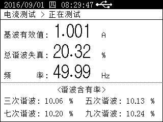
Figure 12
On the "Current Test" screen, simple harmonic analysis can be performed on current data to help users analyze power quality.
Similar Product Recommend