-
E-mail
1815108006@qq.com
-
Phone
13855073989
-
Address
No. 20 Renhe South Road, Tianchang City, Anhui Province
Product Categories
Anhui Tiankang (Group) Co., Ltd. Marketing Center

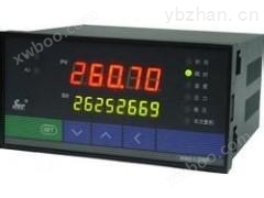
Thermocouple temperature measurement display instrument XMZ-201
NegotiableUpdate on 04/12
- Model
- Nature of the Manufacturer
- Producers
- Product Category
- Place of Origin
Overview
The external dimensions of the XMZ-201 thermocouple temperature measurement display instrument are 160 * 80 * 175 (mm). The square meter is 96 * 96 * 150 (mm)
Product Details
I. Overview
XMZ/T series digital display regulatorProduced according to the standard "Digital Indicators for Industrial Process Measurement and Control Systems", and adopting a novel and innovative circuit design principle and structural form. Due to its simple structure and wiring, it has high reliability, good seismic resistance, and easy use and maintenance.
This instrument has a constant current output function of 0-10mA or 4-20mA, which can be combined with an actuator to form a simple control system, or directly connected to a computer to form an automatic control system without the need for a transmitter, providing convenience for industrial process multi parameter control. It also has two position and three position time proportional PID adjustment functions.
This instrument is suitable for measuring and controlling various parameters in industrial processes. Can be used in conjunction with the following sensors and transmitters or receive the following signals. Display the measured physical quantity directly with numbers.
a、 Thermocouples or radiation thermometers;
b、 Sensors that generate resistance changes through thermal resistance;
c、 Hall pressure transmitter or sensing transmitter that generates DC changes;
d、 Resistance remote transmission pressure gauge;
e、 Standardized analog DC electrical signals (Type II, Type III) or other DC signals.
2、 Main technical indicators
1. Usage, disk mounted. (There are three types: horizontal, vertical, and square)
2. Instruction method: 3? LED digital display with a large reading of 1999.
3. Model specifications: The model specifications are shown in the table below; The measurement range is shown in the table below.
4. Basic error: ± 0.5% F · S ± 1. (F · S is the display range)
5. Resolution: below 0.1 ° C | above 1 ° C | below 200 ° C. (Other physical quantities are the last word)
6. Large wave momentum: less than two resolution values (measured by the deviation of the wave from the midpoint of the wave).
7. Zero drift: Within one hour, the zero drift is less than one-fifth of the basic error.
8. After continuous operation, the error still meets the requirements.
9. Dimensions: 160 * 80 * 175 (mm). The square meter is 96 * 96 * 150 (mm).
10. Hole size: Horizontal 152 * 76 (mm). The vertical dimension is 76 * 152 (mm). The square meter is 90 * 90 (mm).
11. Working power supply: 220V. 50HZ ± 10%.
12. Weight: 1.25kg.
13. Working environment: Temperature range of -10 to 50 ℃, relative humidity not exceeding ± 90%
14. Positional control; Set the range to the full range; The control error is less than ± 0.5% F · S ± 1 word. Output contact capacity: 220V, 3A. (Communication without sensory load).
15. Constant current output: The load capacity is 0-1.5k Ω for 0-10mA, 0-450 Ω for 4-20mA, and the output accuracy is less than ± 0.5% F · S.
three、XMZ Series Digital Indicator Adjustment Instrument Type Spectrograph
| Model | Supporting signal | Additional features |
| XMZ-101 | Thermocouple type | none |
| XMZ-102 | Thermal resistance class | |
| XMZ-103 | MV transmitter | |
| XMZ-104 | Remote Pressure Gauge | |
| XMZ-105 | Type II and III transmitters | |
| XMT-101 | Thermocouple type | Two position adjustment or upper limit alarm |
| XMT-102 | Thermal resistance class | |
| XMT-103 | MV transmitter | |
| XMT-104 | Remote Pressure Gauge | |
| XMT-105 | Type II and III transmitters | |
| XMT-111 | Thermocouple type | Three position narrow band adjustment |
| XMT-112 | Thermal resistance class | |
| XMT-113 | MV transmitter | |
| XMT-114 | Remote Pressure Gauge | |
| XMT-115 | Type II and III transmitters | |
| XMT-121 | Thermocouple type | Three digit broadband adjustment or upper and lower limit alarm |
| XMT-122 | Thermal resistance class | |
| XMT-123 | MV transmitter | |
| XMT-124 | Remote Pressure Gauge | |
| XMT-125 | Type II and III transmitters | |
| XMT-131 | Thermocouple type | Time ratio adjustment Proportional band: 2-30% adjustable Switching cycle: 30 ± 10S |
| XMT-132 | Thermal resistance class | |
| XMT-133 | MV transmitter | |
| XMT-134 | Remote Pressure Gauge | |
| XMT-135 | Type II and III transmitters | |
| XMT-141 | Thermocouple type | Two position PID regulation |
| XMT-142 | Thermal resistance class | |
| XMT-143 | MV transmitter | |
| XMT-144 | Remote Pressure Gauge | |
| XMT-145 | Type II and III transmitters | |
| XMT-151 | Thermocouple type | Time ratio adjustment with upper or lower limit alarm |
| XMT-152 | Thermal resistance class | |
| XMT-153 | MV transmitter | |
| XMT-154 | Remote Pressure Gauge | |
| XMT-155 | Type II and III transmitters | |
| XMT-161 | Thermocouple type | Continuous PID regulation with upper or lower limit alarm |
| XMT-162 | Thermal resistance class | |
| XMT-163 | MV transmitter | |
| XMT-164 | Remote Pressure Gauge | |
| XMT-165 | Type II and III transmitters | |
| XMT-171 | Thermocouple type |
Two position PID regulation with upper or lower limit call the police |
| XMT-172 | Thermal resistance class | |
| XMT-173 | MV transmitter | |
| XMT-174 | Remote Pressure Gauge | |
| XMT-175 | Type II and III transmitters | |
| XMT-191 | Thermocouple type | Continuous PID regulation of 0-10mA or 4-20mA |
| XMT-192 | Thermal resistance class | |
| XMT-193 | MV transmitter | |
| XMT-194 | Remote Pressure Gauge | |
| XMT-195 | Type II and III transmitters | |
| XMZ-201 | Thermocouple type | Equipped with 0-10mA or 4-20mA |
| XMZ-202 | Thermal resistance class | |
| XMZ-203 | MV transmitter | |
| XMZ-204 | Remote Pressure Gauge | |
| XMZ-205 | Type II and III transmitters | |
| XMT-201 | Thermocouple type |
0-10mA or 4-20mA output, with two bits adjust |
| XMT-202 | Thermal resistance class | |
| XMT-203 | MV transmitter | |
| XMT-204 | Remote Pressure Gauge | |
| XMT-205 | Type II and III transmitters | |
| XMT-211 | Thermocouple type |
0-10mA or 4-20mA output, with three bits Narrow band adjustment |
| XMT-212 | Thermal resistance class | |
| XMT-213 | MV transmitter | |
| XMT-214 | Remote Pressure Gauge | |
| XMT-215 | Type II and III transmitters | |
| XMT-221 | Thermocouple type |
0-10mA or 4-20mA output, with three bits Broadband regulation |
| XMT-222 | Thermal resistance class | |
| XMT-223 | MV transmitter | |
| XMT-224 | Remote Pressure Gauge | |
| XMT-225 | Type II and III transmitters | |
| XMT-231 | Thermocouple type | 0-10mA or 4-20mA output with time proportional adjustment |
| XMT-232 | Thermal resistance class | |
| XMT-233 | MV transmitter | |
| XMT-234 | Remote Pressure Gauge | |
| XMT-235 | Type II and III transmitters | |
| XMT-241 | Thermocouple type | 0-10mA or 4-20mA output, with two bits PID control |
| XMT-242 | Thermal resistance class | |
| XMT-243 | MV transmitter | |
| XMT-244 | Remote Pressure Gauge | |
| XMT-245 | Type II and III transmitters | |
| XMT-291 | Thermocouple type |
0-10mA or 4-20mA output, with continuous PID control |
| XMT-292 | Thermal resistance class | |
| XMT-293 | MV transmitter | |
| XMT-294 | Remote Pressure Gauge | |
| XMZ-395 | Type II and III transmitters | |
| XMT-305 | Thermocouple type | Equipped with a power output of 24V. Equipped with a two-wire transmitter. |
| XMT-305 | Thermal resistance class | |
| XMT-315 | MV transmitter | |
| XMT-325 | Remote Pressure Gauge | |
| XMT-335 | Type II and III transmitters | |
| XMT-345 | Two position PID regulation |
Equipped with a 24V power supply. Equipped with a two-wire transmitter. |
| XMT-355 | Time proportion with upper limit alarm | |
| XMT-365 | Continuous PID with upper limit alarm | |
| XMT-375 | Position based PID with upper limit alarm | |
| XMT-395 | Continuous PID regulation | |
| XMT-405 | single display |
Equipped with 24V power supply. Output with two-wire transmitter Equipped with 0-10mA or 4-20mA output. |
| XMT-405 | Two position adjustment | |
| XMT-415 | Three position narrow band adjustment | |
| XMT-425 | Three digit broadband adjustment | |
| XMT-435 | Time proportional adjustment | |
| XMT-445 | Two position PID regulation | With power output 24V Equipped with a two-wire transmitter. |
| XMT-455 | Time proportion with upper limit alarm | |
| XMT-465 | Continuous PID with upper limit alarm | |
| XMT-475 | Position PID with alarm | |
| XMT-495 | Continuous PID regulation |
four、XM series digital display regulator measurement range
| Sensor category | graduation mark | measurement range |
| Nickel chromium nickel silicon | K Eu-2 | 0~600℃; 0~1100℃; 0~1300℃ |
| Nickel chromium copper | EA-2 | 0~300℃; 0~500℃; 0~600℃; |
| Nickel chromium constantan | E | 0~300℃; 0~500℃; 0~800℃; |
| Platinum rhodium 10platinum | S LB-3 | 0~1300℃; 600~1600℃ |
| platinum-rhodium30-Platinum rhodium6 | B LL-2 | 800~1800℃; 1000~1800℃ |
| Radiation thermometer | F2 | 700~1400℃; 1200~1800℃ |
| Copper thermistor | GR0= 53Ω | 0~50℃; 0~100℃; 0~150℃ |
| Cu50R0= 50 Ω | 0~50℃; 0~100℃; 0~150℃ | |
| platinum resistance thermometer | Pt100R0= 100Ω BA2R0= 100Ω BA1R0= 46Ω |
-200~200℃; -100~100℃; 100~150℃; -50~50℃; -50~100℃; -50~150℃; 0~100℃; 0~150℃; 0~200℃; 0~300℃; 0~400℃; 0~500℃; 0~600℃; |
| Pt10R0= 10Ω | 0~10℃; 0~150℃; 0~200℃; | |
Hall pressure transmitter, resistance remote transmission pressure gauge, type II, type III transmitter, and other types of transmitters |
Display pressure (MPa) or vacuum degree, percentage content, and other physical quantities. |
0~0.100; 0.160; 0.250; 0.400; 0.500; 0.600; 1.000; 1.600; 2.50; 4.00; 6.00; ten 16.00; 25.0; 40.0; 60.0; one hundred |
| Display traffic (T/h) | 0~500; 10.00; 16.00; 30.0; 50.0; ten 500; 1000; 1600; one thousand and eight hundred |
Note: 1. Generally, new division marks are used for ordering, and the ones in parentheses are old division marks. If the user needs special ordering treatment. 2. The specifications listed in Table 2 for measurement range are for reference only, and users can indicate them when ordering as needed. 3. When ordering remote transmission pressure gauges, the input signal range category, display range, and unit symbol should be specified. The various physical parameters being measured are converted into voltage, resistance, and current inputs through sensors or transmitters, and then converted into a unified M-signal through the input circuit. The signal is then amplified by an amplifier and linearized to form a linear relationship between the measured and the signal. Finally, it is divided into three output circuits for output. Send A/D analog-to-digital converter all the way. The converter has circuits such as decoding driver, auto zeroing, polarity display, etc., which directly drive the LED for digital display of the measured object. Send V/I conversion and power amplification along the way, with constant current output. Another way is to compare the comparison circuit with the set value and adjust the output in the form of a contact signal through the execution circuit.
Similar Product Recommend