| |
Overview
The SDS series jet fans have specifications ranging from 630mm to 1600mm, and are divided into two categories: unidirectional axial flow fans and reversible (bidirectional) axial flow fans. They have a thrust of 3500N and can choose high-efficiency and low-noise fans for any load and working condition.
The SDS series jet ventilation fan adopts * technology to achieve good quality assurance. The fan housing is formed by spinning and flanging with a special machine tool imported from the United States, and the inner wall of the impeller section is machined with gold to ensure the coaxiality and strength of the housing, as well as the radial clearance of the blades. The outer surface is treated with hot-dip galvanizing or other equivalent coatings, which is beautiful and corrosion-resistant, with excellent performance. The fan blades and hub are processed into die-casting mold cavities using Toshiba's fully automatic CNC boring and milling machining center in Japan. Aluminum alloy high (low) die-casting is carried out in high-pressure casting and low-pressure casting machines, and it has been proven by users in highway tunnels, railway tunnels, water conservancy dam projects, etc. that the fan has various performance indicators, corrosion resistance, reliability, economy and other technical, quality requirements and economic factors. The indicators are fully adapted to the use of various tunnels and subways.
Product Usage Description
In the construction of basic engineering projects such as subways, highway tunnels, and railway tunnels, the air quality standards and safety factors are met through forced ventilation by fans. As for the ventilation system, it is necessary to maintain good air quality for a long time, otherwise it is harmful to the human body, as shown in the diagram.
Design and Product Selection Basis for Tunnel Ventilation System
Transportation tunnels can generally be divided into three categories: subway tunnels, highway tunnels, and railway tunnels.
The prerequisite for the safety and reliability of regular and emergency operations is the installation of an environmental control system that ensures coordination and full functionality among various systems.
A mechanical system: ventilation, fire protection, sewage discharge B power system: power supply, transmission and distribution, emergency power
C Lighting system: continuous lighting, local lighting, fluorescent indication D Communication system: telephone, radio, computer terminal
E Transportation system: lighting, signals, signs, monitoring F Control system: monitoring of traffic conditions, equipment conditions, and equipment operation conditions
The tunnel ventilation system can have the following three basic methods or can adopt a mixed method.
Vertical ventilation system: This is the most basic ventilation method. The fresh air flow flows from the entrance end to the exit end of the tunnel, and there is no need to install ventilation ducts along the longitudinal direction of the tunnel. This ventilation method generally uses reversible jet fans. Install the fan at the top or side of the tunnel to achieve comprehensive ventilation in both directions, achieving bidirectional ventilation or smoke control; If the tunnel is long, additional air supply and exhaust shafts must be added, which are connected to the atmosphere to form a mixed ventilation system.
2. Full horizontal ventilation system: Install air supply and exhaust ducts along the tunnel direction, with fresh air collected from the wind pavilion and exhaust air discharged from the wind tower. Generally, the air supply duct is set below the road surface, and the exhaust duct is set at the upper part of the lane. The air supply duct and exhaust duct are equipped with air supply and exhaust outlets at regular intervals. In case of accidents, exhaust air is promptly discharged along the tunnel cross-section to extract smoke.
3. Semi transverse ventilation system: This system can be divided into supply type semi transverse ventilation and exhaust type semi transverse ventilation. Generally, exhaust type semi transverse ventilation is used, with fresh air entering from the opening and exhaust similar to a full transverse ventilation system.
Factors to consider for tunnel ventilation system:
A Project Investment B Power Capacity C Operating Costs D Air Quality E Safety Factors F Guarantee Measures in Emergency Situations
After comprehensive economic analysis of the above factors, a standardized plan will be established
5. Factors for selecting the number and number of ventilation fans in tunnel ventilation systems:
A CO, NOx, and smoke concentration B Vehicle flow rate (vehicle density, speed)
C Wind load (tunnel length * width * height) D Exhaust emissions (vehicle age, quantity)
Emergency measures in case of fire alarm in E
6. Theoretical basis for thrust calculation of tunnel ventilation system
1. Calculation basis for thrust of tunnel ventilation system
Loss of inlet and outlet resistance? Friction coefficient of tunnel surface and equipment, etc
Vehicle friction coefficient (calculating vehicle motion or piston wind effect under the most unfavorable conditions)
What is the impact of wind speed outside the tunnel on the entrance and exit under the most unfavorable conditions? Tunnel terrain and location (slope, altitude)
The required thrust (temperature, pressure, time) in the event of a fire alarm
Theoretical conversion of 2 tunnel depressurization (Pa) to thrust required by jet fan (N)
The thrust of a jet fan is the change in momentum between the inlet and outlet of the fan, i.e. the fan thrust
N=C * mass flow rate * airflow velocity (N)
In the formula: N=wind turbine static thrust (LSO) N value C=empirical correction factor
Mass flow rate=air density * volumetric flow rate
The relative velocity between the jet fan used in the tunnel and the airflow inside the tunnel, the friction coefficient inside the tunnel, and the influence of parallel arrangement within the same group are all related. Therefore, the effective thrust of the jet fan is:
N=N*(1-V/V)C*C
In the formula: N=effective thrust of the fan (N) V=wind speed inside the tunnel (m/s)
V=Jet velocity (m/s) C=Friction coefficient inside the tunnel
C=Flow loss in parallel arrangement of the same group (this loss can be ignored if the fan units are separated by 100 times the diameter of the fan, so that the jet velocity does not affect the operating conditions in the direction of the air flow).
7. Structural characteristics of ventilation fans used in tunnel ventilation systems
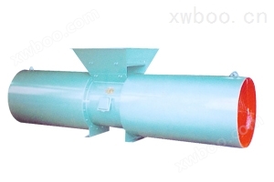
Tunnel ventilation fans are divided into two ventilation forms: unidirectional jet fan (SDS) and bidirectional jet fan (SDS (R))
The fan body, muffler, and bracket feet are made of steel plate CNC automatic welding and mechanism forming, and the surface is treated with surface coating to ensure the strength and corrosion resistance of the fan
Fan impeller: To meet the needs of tunnel ventilation, the SDS series fan can change the number of blades and the angle of the fan blades
Muffler: The length of the muffler is usually twice the diameter of the fan. When noise requirements are high, it can also be twice the diameter of the fan. The muffler is fixed to the fan body with bolts.
Supporting motor: The SDS series jet ventilation fan is equipped with a squirrel cage fully enclosed motor, which is equipped with a flange mounting plate. The motor has an insulation level of H and an anti-corrosion level of IP55. The motor's lead out cable can be connected to the junction box on the fan body casing. The motor is equipped with a lubricating grease nozzle, and an external metal hose is connected to the lubricating grease nozzle on the fan body casing.
Reversible switching time of the fan: In emergency situations, the forward and reverse switching time of the jet fan is extremely important. The SDS (R) fan has two switching methods: electronic and mechanical, which can switch forward and backward to the rated speed of the fan within 30 seconds.
SDS series jet ventilation fan testing and inspection
Thrust test: measured using a thrust test device.
High temperature fire test conducted by Tianjin Fire Test and Inspection Center.
Noise testing: Both the inlet and outlet of the fan with and without mufflers were tested in an open area (when the atmospheric wind speed was close to 0). The sound pressure level of the fan was measured at a 45 ° angle along the fan axis, 10m away from the fan.
Fan efficiency: The operating efficiency of the fan is defined by measuring the thrust (N) and motor input power (KW).
The experimental testing is strictly conducted by the Engineering Technology Center (Experimental Research Center) of Shangjian Company in accordance with relevant national and industry standards, and has been tested and inspected by provincial and supervisory agencies.
| |


| |