-
E-mail
zydqgf@vip.163.com
-
Phone
17798953999
-
Address
No. 888 Jinbao West Road, Baoying Anyi Industrial Park, Yangzhou, Jiangsu
Product Categories
Jiangsu Zhongyang Electric Co., Ltd


New Zinc Oxide Surge Arrester Tester
NegotiableUpdate on 01/23
- Model
- Nature of the Manufacturer
- Producers
- Product Category
- Place of Origin
Overview
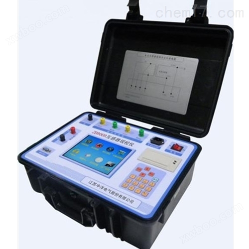
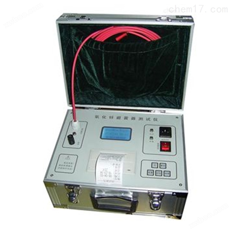
The new zinc oxide lightning arrester tester has been improved by our company based on on-site measurement needs. It combines DC high-voltage power supply, measurement and control system organically, reducing the size and weight of the instrument. Humanized operation settings, remote control measurement is achieved through remote control, and automatic measurement of environmental temperature function is added according to measurement regulations. It has a large capacity storage, which can store 50 sets of test data without loss in case of power failure. Equipped with a high-speed thermal printer greatly improves the printing speed of test results. It is equipment used for on-site inspection of power systems and zinc oxide lightning arrester operating plants.
Product Details
New Zinc Oxide Surge Arrester TesterMeasurement principle:
After the input current and voltage are digitally filtered, the fundamental wave is extracted, and then the peak value of the resistive current fundamental wave Ir1p=Ix1p. cos φ is calculated using projection method. Due to the stability of the fundamental wave value, Ir1p is commonly used to measure the performance of lightning arresters.
The peak value Ix1p of the total current fundamental wave is projected as Ir1p in the direction of the voltage fundamental wave U1 (E1), and as Ic1p in the vertical direction. The phase angle of the current and voltage fundamental waves is denoted as φ, which includes the selected compensation angle (Figure 7). Therefore, both φ and Ir1p can be used to intuitively measure MOA performance.
interference between phases
2. During on-site measurement, the lightning arrester arranged in a straight line (Figure 8) is affected by stray capacitance in the middle B phase, which affects the leakage current of A and C phases, causing a decrease in phase A diameter, an increase in resistive current, an increase in phase C diameter, a decrease in resistive current, or even negative. This phenomenon is called phase to phase interference (Figure 9).
One method is to compensate for phase to phase interference: assuming that Ia and Ic have no interference, the phase difference is 120 °, and assuming that B is the same relative to phase A and C interference;
Take the voltage as phase B and the current as phase C, and measure that φ 1=φ cb; Take the current as phase A again, and measure that φ 1=φ ab; The phase difference between the C-phase current and the A-phase current is denoted as φ ca=φ cb - φ ab;
3. Select the correction angle D φ=(φ ca -120 °)/2, and put this value into the instrument in the main menu; Choose the appropriate phase sequence, and the instrument will automatically compensate for the angle based on the selected phase sequence (A adds D φ, B phase does not need to be compensated and chooses 0, C subtracts D φ). It is also not necessary to compensate for phase to phase interference (i.e. compensating for angle of 0), and the performance of the lightning arrester can be judged based on the trend of resistive current changes. If allowed, only add electricity to the test to obtain data. And laboratory measurements do not need to consider phase to phase interference

New Zinc Oxide Surge Arrester TesterNotes:
When taking the reference voltage from the PT secondary, the wiring should be carefully checked to avoid PT secondary short circuit.
2. The voltage signal input line and current signal input line must not be connected in reverse. If the current signal input line is connected to the PT secondary side or the measuring end of the test transformer, it may burn out the instrument.
3. Do not plug or unplug the measuring wire in the presence of input voltage and current to avoid burning out the instrument.
After the instrument is damaged, please stop using it immediately and notify the relevant units. Do not open the box for repair by yourself. When the instrument is not working properly, please first check if the power fuse is blown. The experiment can only continue after replacing the insurance with the same model.
5. This instrument should not be placed in damp or excessively hot environments.
When taking the reference voltage from the PT or the measuring end of the test transformer, the wiring should be carefully checked to avoid PT secondary or test voltage short circuits.
7. Be careful not to connect the current and voltage sampling lines incorrectly during the wiring process.
When conducting experiments in the laboratory, the high-voltage power supply cannot use a series test transformer.
Main issues:
1. Due to the elimination of the series gap, the instrument can withstand system voltage and current flow. The active component of the current in the valve plate heats up, causing changes in the volt ampere characteristics, which can lead to valve plate aging and even thermal breakdown.
2. When the instrument is subjected to impulse voltage, the valve plate will also age under the action of impulse voltage energy.
3. Moisture or poor insulation performance inside the instrument can increase the power frequency current, intensify power consumption, and in severe cases, lead to internal discharge.
4. The instrument is contaminated by rain, snow, condensation, or dust, resulting in a significant potential difference between the internal valve plate and the external ceramic sleeve due to different internal and external electrical discharges, leading to radial discharge phenomena.
Technical Specifications:
1. Power supply: 220V, 50Hz or internal power supply.
2. Reference voltage input range (voltage reference signal): 50Hz, 30V~100V.
Measurement parameters:
3. Leakage current full current waveform, fundamental effective value, and peak value.
4. The fundamental effective value and 3rd, 5th, and 7th effective values of the resistive component of the leakage current.
5. Peak values of resistive components of leakage current: positive peak value Ir+, negative peak value Ir -.
6. Fundamental wave of capacitive current, phase difference between full voltage and full current.
7. Effective value of operating (or testing) voltage.