-
E-mail
2880125172@qq.com
-
Phone
13819775961
-
Address
5th Floor, No. 66 Liujiang North Road, Liushi Town, Yueqing, Zhejiang
Product Categories
Yueqing Nanrui Huaning Automation Equipment Co., Ltd
Microcomputer harmonic elimination device
NegotiableUpdate on 01/21
- Model
- Nature of the Manufacturer
- Producers
- Product Category
- Place of Origin
Overview
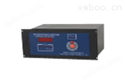
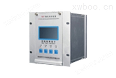
Microcomputer harmonic elimination device 1. Overview WDP series microcomputer harmonic elimination device is an intelligent harmonic elimination device developed by our company for the malignant accidents of voltage transformer (PT) burning or even exploding that often occur in the power sector and users due to ferromagnetic harmonic elimination
Product Details
Microcomputer harmonic elimination device

1、 Device Overview
The WDP series microcomputer harmonic elimination device is an intelligent harmonic elimination device developed by our company to address the malignant accidents of voltage transformer (PT) burnout and even explosion that often occur in the power sector and users due to ferromagnetic harmonic elimination. This device utilizes an ARM processor as the core processing component, which has the advantages of stable performance and strong resistance to power. Not only can it eliminate ferromagnetic resonance, but it can also provide alarm indications for overvoltage and single-phase grounding.
2、 Model Description

3、 Technical indicators
(1) Working power supply: AC/DC80~250V, power consumption less than 15W;
(2) Environmental temperature: -45 ℃ to+50 ℃;
(3) Environmental humidity: not exceeding 90% RH;
(4) Eliminating resonant frequencies: 17Hz (1/3 division), 25Hz (1/2 division), 50Hz (power frequency), 150Hz (3rd harmonic), 300Hz (6th harmonic).
4、 Device features
(1) Suitable for various voltage levels and resonant frequencies (1/3 division, 1/2 division, power frequency, 3rd harmonic, 6th harmonic) with a wide range of applications;
(2) No need for tuning and debugging, automatically enters the running state after startup, with minimal maintenance;
(3) Distinguishable between ferromagnetic resonance, overvoltage, and single-phase grounding;
(4) Automatic display, recording the occurrence time and related parameters (resonance frequency, amplitude) of single-phase grounding and ferromagnetic resonance;
(5) It can store 100 fault information for recall and display, and data will not be lost for 100 years after power failure;
(6) Configurable RS485 communication interface, standard MODBUS protocol;
(7) All alarm signals are provided with relay contact outputs.
5、 Hardware composition of the device
1. Power Supply: This device uses a high-frequency switching power supply, which has strong resistance and allows for a large range of input voltage fluctuations. The output voltage is DC+5V, ± 12V.
2. The control center of the device adopts ARM processors, which have strong control capabilities and operate safely and reliably. And it is equipped with an internal monitoring timer, which can free the system from crashes caused by software failures at any time, providing a guarantee for long-term safe and reliable operation;
3. Data storage, using Flash storage chips, has the advantages of large storage capacity and no data loss in case of power failure;
4. Data acquisition part: Its function is to convert analog signals into digital signals for computer processing;
5. Display section: Used as a clock under normal system conditions, it can display relevant fault information when the system malfunctions;
6. Harmonic elimination control: Control the harmonic elimination circuit and activate high-power harmonic elimination components to quickly eliminate ferromagnetic resonances of various frequencies.
6、 Working principle of the device
This device uses ARM processor as the core component to perform loop detection on PT open delta voltage (i.e. zero sequence voltage). Under normal operating conditions, if the voltage is less than 30V, the high-power harmonic elimination component (thyristor) inside the device is in a blocked state and has no impact on the system. When the voltage of the PT opening triangle is greater than 30V, it indicates that the system has malfunctioned. The device begins to collect data on the open delta voltage. By using digital signal processing techniques such as digital measurement, filtering, and amplification, the data is analyzed and calculated to determine the current fault state. If a certain frequency of ferromagnetic resonance occurs, the CPU immediately starts the harmonic elimination circuit (making the thyristor conductive) to quickly eliminate the ferromagnetic resonance under strong damping. After the elimination of ferromagnetic resonance, the CPU makes corresponding records, stores, and automatically alarms and displays relevant resonance information (including occurrence time, frequency, amplitude, etc.). If it is overvoltage or single-phase grounding, after the CPU makes a diagnosis, the device will display and alarm separately, and automatically record and store relevant fault information. Finally, the CPU returns to its initial state and continues to detect the open delta voltage.
7、 Software composition of the device
This device uses C language as the programming software, which mainly consists of monitoring program, floating-point operation library, diagnostic software, harmonic elimination, recording and other parts. The real-time monitoring program completes tasks such as voltage detection, sampling, diagnosis, harmonic elimination, clock, keyboard commands, and display. The simple block diagram is shown in Figure 1:

8、 Device installation
This device is installed on the PK screen or in the terminal box, and each device can be connected to 1-4 sections of busbars according to the user's selection. The schematic diagram of the terminal wiring behind the device is shown in Figure 2
(1) 1PT * "and" 1PT "are respectively connected to the same and non same name terminals of the open delta voltage of the section bus." 2PT * "and" 2PT "are respectively connected to the same and non same name terminals of the open delta voltage of the second section bus, and so on;
(2) The "RS485" terminal is a communication terminal that can be directly connected to the RS485 communication bus;
(3) The "power" terminal can be connected to AC power or DC power without polarity, with a voltage range of 80-250V;
(4) The "grounding alarm" terminal is connected to an external alarm signal, and this terminal * is a pair of normally open contacts. Close when the fault occurs and delay for about 1 minute until the fault disappears. Its contact capacity is AC 220V/5A;
(5) The "resonance alarm" terminal is connected to an external alarm signal, and this terminal * is a pair of normally open contacts. When a fault occurs, it closes with a contact capacity of AC 220V/5A.
| Rear terminal diagram of WDP microcomputer harmonic elimination device | |||||
| 1 | 4PT* | 12 | grounding | ||
| 2 | 4PT | 13 | power supply | ||
| 3 | 3PT* | 14 | power supply | ||
| 4 | 3PT | ||||
| 5 | 2PT* | ||||
| 6 | 2PT | ||||
| 7 | 1PT* | 15 | Resonance alarm 4 | ||
| 8 | 1PT | 16 | Resonance alarm 3 | ||
| 17 | Resonance alarm 2 | ||||
| 18 | Resonance alarm 1 | ||||
| 19 | Resonance alarm common terminal | ||||
| 9 | RS485 ground | 20 | Grounding alarm 4 | ||
| 10 | RS485B | 21 | Grounding alarm 3 | ||
| 11 | RS485A | 22 | Grounding alarm 2 | ||
| 23 | Grounding alarm 1 | ||||
| 24 | Grounding alarm common terminal | ||||
9、 Instructions for use
1. Device startup display:
Microcomputer harmonic elimination device
2009-09-30
09:59:30
2. Press the "Menu/Confirm" button, and the LCD panel will display:
adjust the time
Adjust the starting voltage
Communication parameter settings
Query fault records
3. The cursor can be moved using the "↑/+" and "↓/-" buttons
adjust the time
Adjust the starting voltage
Communication parameter settings
Query fault records
4. When the cursor selects "Adjust Time", press the "Menu/Confirm" button, and the LCD panel displays as follows:
adjust the time
2009-09-30 10:02
The number selected by the cursor can be adjusted using the "↑/+" and "↓/-" buttons. After adjustment, press the "Menu/Confirm" button, and the device will display as follows:
adjust the time
2010-09-30 10:02
The adjustment method is as described earlier. After all adjustments are completed, the device displays as follows:
adjust the time
2010-10-10 11:59
Press the 'Cancel' button to exit the time adjustment.
5. When the cursor selects "Adjust startup voltage", press the "Menu/Confirm" button, and the LCD panel displays as follows:
1 section grounded 30V
1-stage resonance 100V
2-segment grounding 30V
2-stage resonance 100V
The number selected by the cursor can be adjusted using the "↑/+" and "↓/-" buttons. After adjustment, press the "Menu/Confirm" button, and the device will display as follows:
1 section grounded 30V
1-stage resonance 100V
2-segment grounding 30V
2-stage resonance 100V
By analogy, the grounding and resonant operating voltages of all busbars can be adjusted. When all are adjusted, press the "Cancel" button to exit the "Adjust Starting Voltage" menu;
6. When the cursor selects "Communication Parameter Settings", press the "Menu/Confirm" button, and the LCD panel will display as follows:
Communication parameter settings
Baud rate 9600V
Local Address 1
There are "600/1200/2400/4800/9600/14400/28800" baud rates available for selection. The selected number can be adjusted by pressing the "↑/+" and "↓/-" buttons. After adjustment, press the "Menu/Confirm" button, and the device will display as follows:
Communication parameter settings
Baud rate 9600V
Local Address 1
The communication address can be selected from 0-255. After adjustment, press the "Menu/Confirm" button to confirm the adjustment, and press the "Cancel" button to exit the "Communication Parameter Settings" menu;
7. When the cursor selects "View Fault Record", press the "Menu/Confirm" button, and the LCD panel will display as follows:
1 Mother Resonant 1/45
2009-09-30 09:23
Voltage: 150.0V
Frequency: 50Hz
You can view the device's fault records by pressing the "↑/+" and "↓/-" buttons. Press the "Cancel" button to exit the "Communication Parameter Settings" menu.
8. Press the 'Cancel' button for 5 seconds to clear all fault records of the device. The LCD panel displays the following:
Record cleared
10、 Installation method of the device
The device adopts embedded installation method, and the opening size is as follows:

Similar Product Recommend