-
E-mail
2880125172@qq.com
-
Phone
13819775961
-
Address
5th Floor, No. 66 Liujiang North Road, Liushi Town, Yueqing, Zhejiang
Product Categories
Yueqing Nanrui Huaning Automation Equipment Co., Ltd
Arc suppression, harmonic suppression, and overvoltage protection
NegotiableUpdate on 01/21
- Model
- Nature of the Manufacturer
- Producers
- Product Category
- Place of Origin
Overview
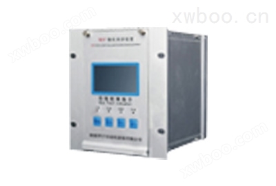
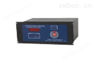
Overview of Arc Suppression and Overvoltage Protection 1: WDP Type Arc Suppression and Overvoltage Protection Device Microcomputer Control Device is a monitoring and operating unit for arc suppression and overvoltage protection devices in 3-35kV neutral point non directly grounded systems. It is a monitoring device based on the control principles of arc suppression and overvoltage protection devices, using a PIC microcontroller as the core processing unit with * * and * * resistance *
Product Details
Arc suppression, harmonic suppression, and overvoltage protection

1 Overview
The WDP type arc suppression, harmonic suppression, and overvoltage protection device microcomputer control device is a monitoring and operating unit for arc suppression, harmonic suppression, line selection, and overvoltage protection devices in 3-35kV neutral point non directly grounded systems. It is a monitoring device based on the control principles of arc suppression, harmonic suppression, line selection, and overvoltage protection devices, using * * and * * resistance * PIC microcontrollers as the core processing unit.
This device adopts a remote centralized control design, which can monitor the arc suppression, harmonic suppression, and overvoltage protection devices in real time, and can also remotely monitor the voltage of the busbar by uploading it.
This device is designed for on-site installation and has the advantages of small size, light weight, good sealing, strong resistance to earthquakes, and good seismic resistance. It is suitable for use in harsh environments.
2. Device Functions and Protection Configuration
This device provides the following protection and related functions:
2.1 Detection and limitation of arc overvoltage;
2.2 Detection and elimination of resonant overvoltage;
2.3 Insulation monitoring (zero sequence voltage detection);
2.4 Voltage Transformer (PT) High Voltage Fuse Melting Detection;
2.5 Voltage transformer (PT) secondary disconnection detection;
2.6 Display of operational data;
2.7 Record the fault characteristic values of 16 events;
2.8 Record data stored in FLASH memory, which can be saved for more than three years when the device is powered off;
2.9 Communication function.
3 Main Technical Data
3.1 Rated parameters:
a. Working voltage: AC220V/DC220V (no polarity requirement)
b. Frequency: 50Hz
3.2 Power consumption:
a. AC voltage circuit:<0.2VA/phase (IN=5A) b. Operating current circuit:<5W
3.3 Measurement accuracy:
a. Voltage measurement error<5%;
b. The time measurement error shall not exceed 20ms. 3.4 Environmental conditions
3.8.1 Basic environmental conditions:
a. Environmental temperature: 40 ± 5 ℃
b. Relative humidity: 45% to 95%
c. Atmospheric pressure: 80-110Kpa (relative altitude of 2km or below).
3.5 Normal working environment conditions: a. Environmental temperature: -20 ℃ to+50 ℃
b. Relative humidity: The monthly average relative humidity is below 95%, and there is no condensation on the surface of the casing.
c. Working environment: There are no corrosive gases or serious dust and mold that can cause damage to metal or insulation, and no substances that pose a fire or explosion hazard.
3.6 Insulation performance:
3.6.1 Insulation resistance: The insulation resistance between each live conductive circuit and the ground (i.e. the shell or exposed non live metal parts) should not be less than 100M Ω when measured with a testing instrument with an open circuit voltage of 500V.
3.6.2 Dielectric strength: Each charged conductive circuit can withstand an AC voltage of 50Hz and 2kV (effective value) between the ground (i.e. shell or exposed non charged metal parts), and there is no breakdown or flashover phenomenon after a 1-minute inspection.
3.6.3 Each input and output live conductive terminal should be grounded, and between the AC circuit and the DC circuit, as well as between the AC current circuit and the AC voltage circuit, it should be able to withstand a standard lightning wave impulse test of 5kV (peak value).
3.7 Anti electrical interference performance:
Capable of withstanding pulse interference testing for attenuated oscillating waves with frequencies of 1MHz and 100kHz (with a half wave voltage amplitude of 2.5kV in common mode and 1kV in differential mode).
3.8 Mechanical properties:
a. Working conditions: able to withstand vibration response and impact response tests with a severity level of I.
b. Transportation conditions: able to withstand vibration durability, impact durability, and collision testing with a severity level of I.
Structure of Device 4
4.1 Structural Description
Structural dimensions: 442 (w) × 175 (H) × 350 (L); Installation method: Embedded.
4.2 Hole size

5、 Instructions for using microcomputer controller

5.1 Meaning of LED Display
When the device is powered on, it immediately enters the running state, and the LED displays the PT secondary phase voltages UA, Ub, Uc in a cyclic manner. As shown in the following figure:

The device body malfunction LED displays E, A (b, c, o) indicates the corresponding input voltage circuit fault, and 01 indicates a fault in the No.1 selection circuit. For example:

■ System resonant LED display:

■ System arc grounding LED display (the fifth digit is phase A, b, C):

■ System direct grounding LED display (01 represents grounding line number, the fifth digit is phase A, b, C)

■ Voltage transformer fuse fuse LED display (the fourth digit is phase A, b, C):

5.2 Key operation
Press the "Clock" button while in operation to view the time and time synchronization.
(1) Press the "Clock" button again, and the LED will display the year, month, and day. Press the "▲" or "▼" button to adjust the date, and press the "Confirm" button to confirm that the adjustment is effective, displaying "y - good".
(2) Press the "Clock" button again, and the LED will display the hour, minute, and second. Press the "▲" or "▼" button to adjust the time, and press the "Confirm" button to confirm that this adjustment is effective, displaying "h-good".
Press the "Set" button in the running state to set the number of line selection circuits and communication address of the device.
(1) Press the "Set" button again, and the LED will display OLC=00. Press the "▲" or "▼" button to adjust the number of line selection circuits, which defaults to 0 at the factory. Press the "Confirm" button to confirm that this adjustment is effective, and the display will show
L—good。
(2) Press the "Settings" button again, and the LED will display "Add=00". Press the "▲" or "▼" button to adjust the communication address, which defaults to 0 at the factory. Press the "Confirm" button to confirm that this adjustment is effective, and the display will show
A—good。
Press the "Query" button while in operation to view the fault records.
(1) Press again to display: number of times (01), fault phase and fault nature. After each press, display in sequence: occurrence date (year, month, day), occurrence time (hour, minute, second), A-phase voltage (peak), B-phase voltage (peak), C-phase voltage (peak).
(2) The number "01" represents the latest fault information. After displaying the fault information once, press again to display the previous (02) fault information.
(3) When the fault information is not displayed, it indicates that * has occurred.
When the isolation knife switch is in the open position and the controller is in operation, press the "test" button to perform the opening and closing test of the single-phase high-voltage contactor.
(1) Press the "Test" button again to display "H-A", press "Confirm" to execute, and display "A-H". Press the 'Confirm' button again to open the circuit and display 'A-F'.
(2) The B, C, D, and E tests are the same as A.
When the stable arc light is grounded, press the "▼" key to reset the arc extinguishing action.
When the system malfunctions or the device triggers an alarm, press the "▼" key to clear the alarm.
In debugging mode, pressing the "confirm" and "exit" keys simultaneously can clear the fault record.
In debugging mode, press the "Exit" button to immediately return to the running state. If no button is pressed for 5 minutes during debugging, it will automatically return to the running state.
During debugging, press the "Reset" and "Confirm" buttons simultaneously to initialize the microcomputer controller of the device. Non professional technicians are not allowed to operate this function.
Attachment Communication Protocol (MODBUS RTU Protocol) Communication Interface: RS485
2. Communication method
① Communication format: Asynchronous, with one start bit, eight data bits, and one stop bit;
② Communication speed: 4800bps;
③ Site selection method: can be set by software, ranging from 00 to 99, with a total of 100 addresses;
⑤ Communication method: The monitoring host and WDP-35 device adopt a one-to-one (or one to many) master-slave query method.
3. Message format:
Address (8 bits) Function code (8 bits) Data area (8 x n bits) Verification code (L) Verification code (H)
Explanation: Address: The address of the substation;
Function code: the function executed by the command substation;
Data area: The address index is used for downlink commands, and the data required by the master station is used for uplink commands;
Verification: CRC verification method.
4. Message exchange
① Inquire about the command issued by the switch system: sub machine address 01, starting address (00), starting address (00), switch quantity (00), switch quantity (28), CRC code (L), CRC code (H)
Device reply message: Address 01 reads byte count (05), fault phase and fault type (BYTE1), fault line (BYTE2, BYTE3, BYTE4, BYTE5), CRC code (L), CRC code (H)
significance:
BYTE1 byte, everyone: D0=1, phase A; D1=1,B; Phase D2=1, Phase C; D3=1, Busbar grounding; D4=1, Arc grounding; D5=1, Metal grounding; D6=1, Resistance grounding; D7=1, resonance. Fault line byte: BYTE2 byte: D0=1 Line 1 grounded, D1=1 Line 2 grounded... BYTE3 byte D0=1 Line 9 grounded, and so on.
② Inquire about analog quantity
System issues command: Machine number 03 Starting address (0 0) Starting address (00) Analog quantity (00) Analog quantity (03) CRC code (L) CRC code (H)
Device reply message: Machine number 03 Analog byte count (06) BYTE1 (H) BYTE1 (L) BYTE2 (H) BYTE2 (L) BYTE3 (H) BYTE3 (L) CRC code (L) CRC code (H)
Meaning: BYTE1, BYTE2, BYTE3, in that order: Ua, Ub, Uc.
Similar Product Recommend