-
E-mail
hengslter@yeah.net
-
Phone
18221776247
-
Address
Pudong New Area, Shanghai
Product Categories
Shanghai Xiangze Machinery Equipment Co., Ltd
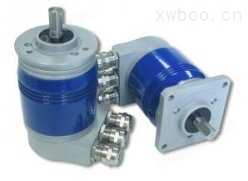
Eltra encoder EAM63 Profibus
NegotiableUpdate on 01/22
- Model
- Nature of the Manufacturer
- Producers
- Product Category
- Place of Origin
Overview
The Eltra encoder EAM63Profibus PR0FIBUS encoder (identification number 0x0599) complies with the PROFIBUSDP standard described in Volume 2 of the European standard EN50170
Product Details
Eltra encoder EAM63 Profibus

The PR0FIBUS encoder (identification number 0x0599) complies with the PROFIBUS DP standard described in Volume 2 of the European standard EN50170. The PR0FIBUS encoder complies with the "PR0FIBUS Device Specification Document" with serial number 3062. The PROFIBUSDP interface has the same characteristics as the encoder and maintains the same resolution (8192 positions/rpm, 4096 turns), adding the features of the PR0FIBUS DP network.
Functions can be achieved through PROFIBUSDP:
Obtain encoder angular position in cyclic data exchange
Set resolution and number of turns per revolution
Set default incremental counting direction
Implement reset operation (set a specific value for an encoder)
Read the diagnostic status
Obtain code information provided at the device level
At the device level, it can achieve:
Display 0N/OFF status, show bus device activity status, set device address
If necessary, connect terminal resistors on the bus to change the counting direction
To install a PR0FIBUS encoder on a network, the standard steps for configuring a PROFIBUSDP slave must be followed. The operation steps are as follows:
1. Slave stations on the main station (see corresponding chapters)
2. Connect the encoder to the PR0FIBUS network, depending on the physical location occupied by the device on the bus at the terminal or middle
3. Directly set the slave address (the address must be on the network, this selection is the same as step 1)
4. Prepare work at the main station and start PR0FIBUS network operation
On the back of the encoder (see figure), there is an LED monitoring window that displays the operating status of the device through two LED windows. As long as there is power, the green light remains on
Circular data exchange between PR0FIBUS master station and encoder, red light off
In the cross-sectional view (as shown in Figure A), there are 2 terminal line jumper switches and 8 device address jumper switches. In the configuration shown in the diagram, the two terminal line contacts are set to OFF, and the encoder is not a terminal of the bus, that is, the terminal resistance is not short circuited.
8 jumper switches are selected with 7 bits to set the slave address, as the maximum number of devices that can be connected in a PR0FIBUS bus is 126.
Contact 8 is LSB and contact 2 is MSB.
The eighth contact (1) is used to invert the encoded code value.
network connection
network connection
In order to connect the encoder to the PROFIBUS network, a bus cover is used to connect the cable inside the encoder (in some cases, only 2 cable connectors are used).
Usually, one cable connector is used to connect the bus, the second cable connector is used to connect the network, and the third one supplies power to the encoder (if power cannot be supplied to the encoder through the PROFIBUS network, RS-485 twisted pair cable is used for power supply).
The use of junction boxes
The use of junction boxes
Note:
To set parameters and configure slaves on the PROFIBUSDP master station, the "Exx_0599. gsd" file provided by the encoder must be used. This document can be downloaded from our company website www.Eltra.it.
| Electrical Characteristics | |
| Multi cycle resolution | 2/4/8/16/32/128/256/512/1024/2048/4096/8192/16384 |
| input voltage | 12~28VDC |
| No load input current | 300mA |
| Bus electronic output configuration | Long line drive (RS485) |
| output frequency | 100KHz output code value F=RPM * resolution/60 |
| precision | +/- 1/2 LSB |
| Bus speed | 12M Porter |
| mechanical properties | |
| Shaft diameter (mm) | Φ6 g6-58B, Φ8 g6-58B-63A/D/E ,Φ9 52(3/8'') g6-63A/D/E-90A, Φ10 g6-58B/C-63A/D/E-90A-115A,Φ11 g6-115A |
| Axis aperture (mm) | Φ8 H7-58F-63F/G, Φ9 H7-58F-63F/G,Φ10 H7-58F-63F/G,Φ12 H7-58F-63F/G,Φ14 H7-58F-63F/G,Φ15 H7-58F-63F/G |
| speed | 6000 continuous 3000 continuous (applicable to 63G/F) 3000 adopts IP66 protection level |
| Axle load | 10N (1Kgf) axial shaft diameter Φ 6 20N (2Kgf) axial shaft diameter Φ 6 100N (10Kgf) axial 00N (10Kgf) radial |
| impact | 50G(11ms) |
| vibration | 10G(10~2000Hz) |
| Bearing lifespan | 109 turns |
| bearing | double row ball bearing |
| shaft material | Stainless steel AISI 303 |
| main material | Aluminum 6060 |
| housing material | Aluminum UNI 9002/5- (D11S) |
| Flange material | Aluminum UNI 9002/5 (D11S) |
| weight | 800g-58B/C-63A/D/E/G 1000g-90A-115A |

![ELTRA Magnetic Encoder SSI Output [EAM 36]](https://img80.xwboo.com/a0e727e8d93ff737abb1977ce195ac2c9a0ab1ed8d0e56c087f57eae2f6434bb83942d993a79e189.jpg)
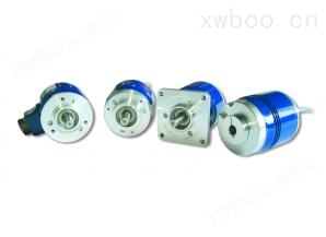
![ELTRA Encoder SSI Output [EAM 63 AX/DX]](https://img77.xwboo.com/a0e727e8d93ff737abb1977ce195ac2c08d48abe839b7b364fb9d5a011068a389a65d8800337b7e7.jpg)