-
E-mail
18317003557@163.com
-
Phone
18317003557
-
Address
Room 319, Building B, Greenland, No. 5558 Chuansha Road, Pudong New Area, Shanghai
Product Categories
Shanghai Xiangrun Industrial Co., Ltd
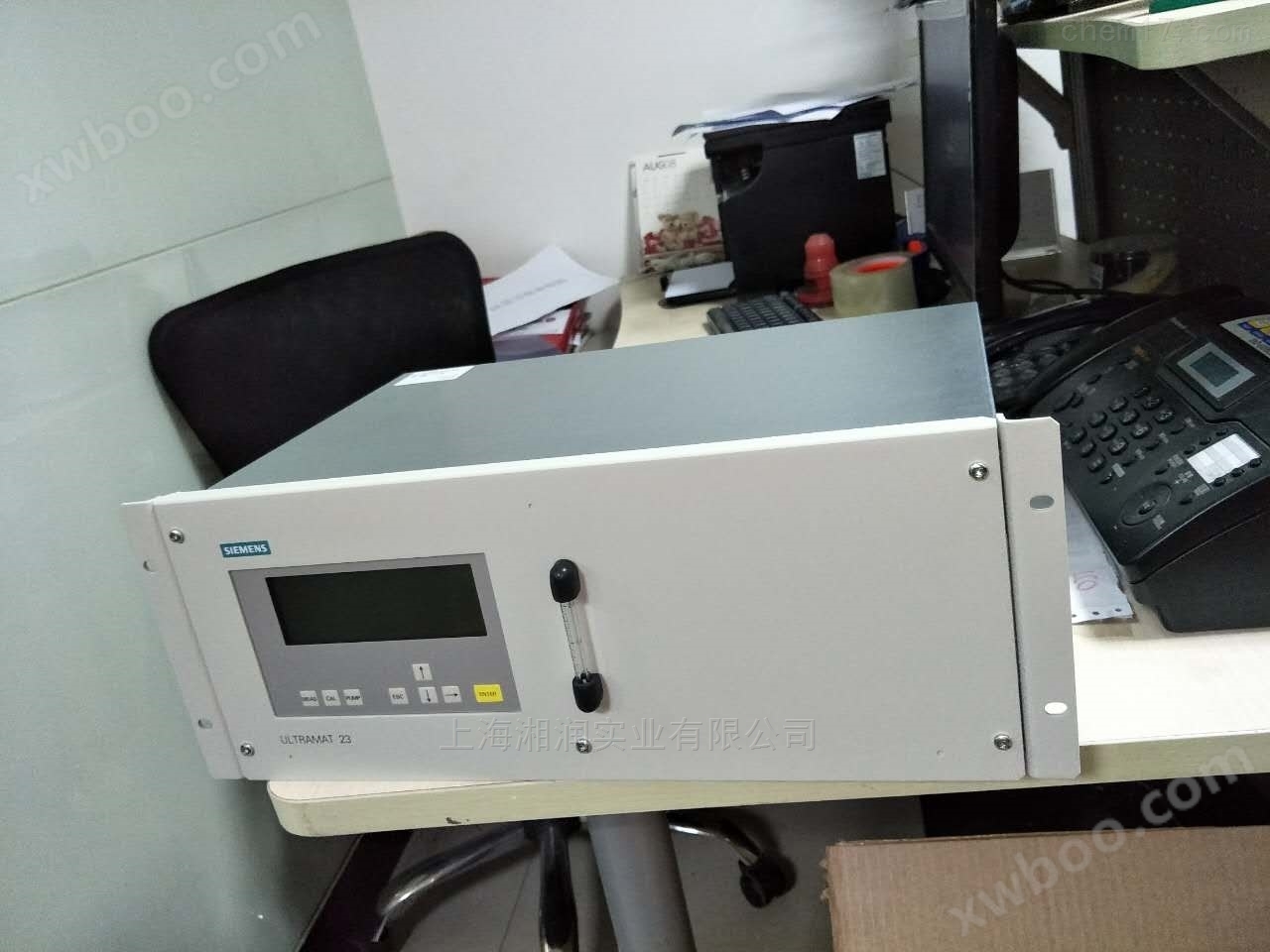

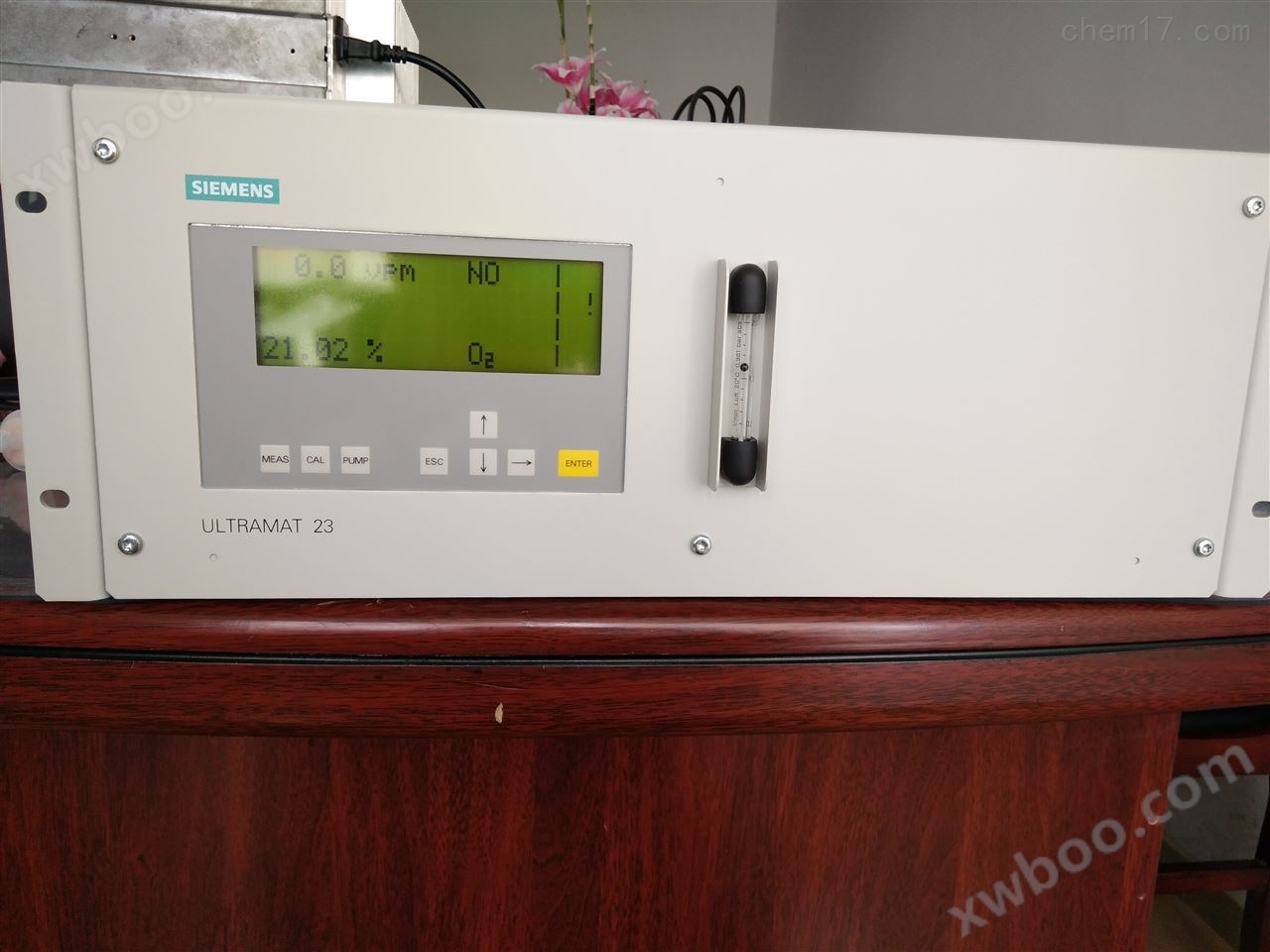
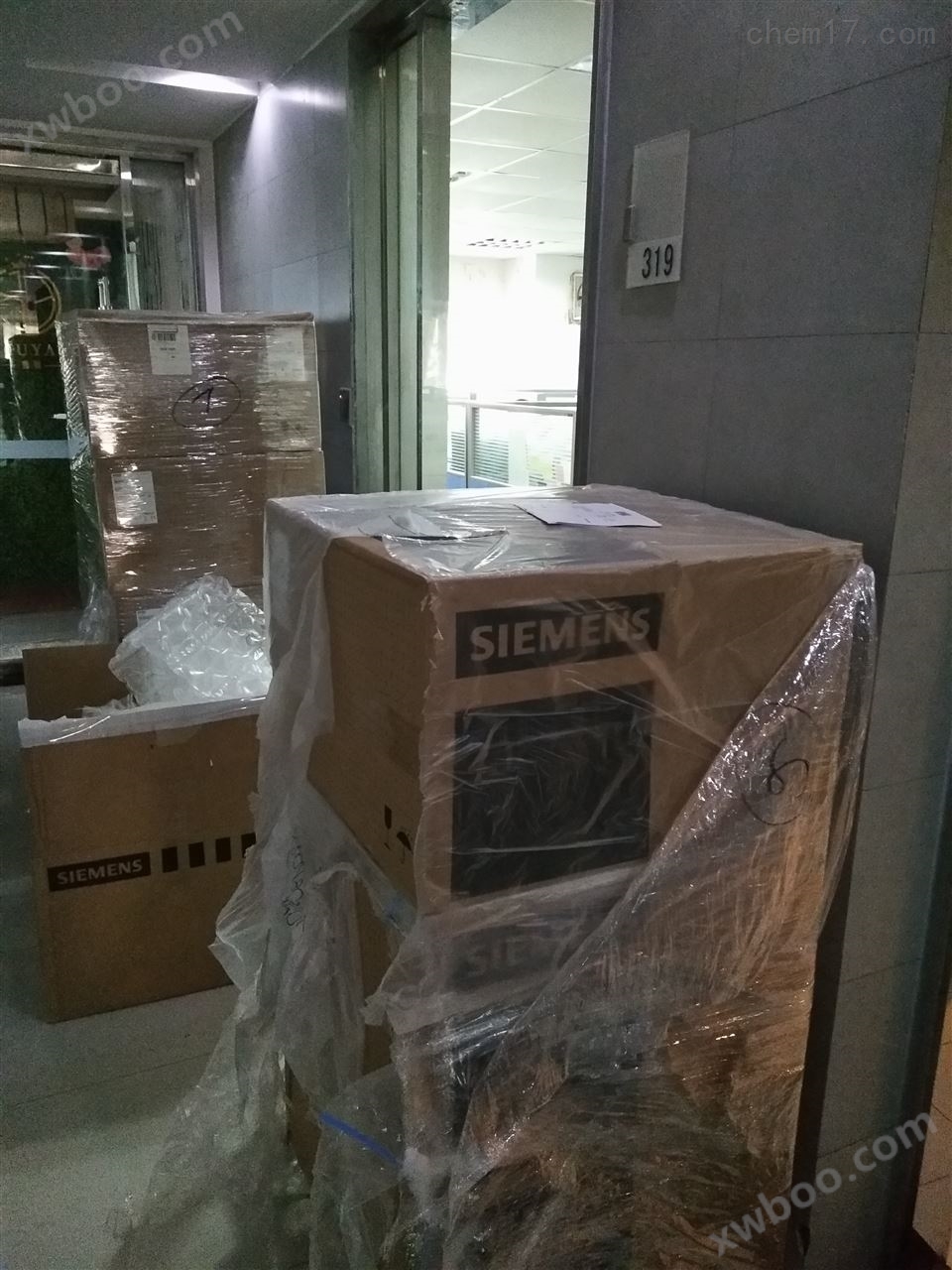
During the epidemic, buying Siemens analyzers and finding good service in Xiangqian is crucial
NegotiableUpdate on 01/21
- Model
- Nature of the Manufacturer
- Producers
- Product Category
- Place of Origin
Overview
7MB2335-0NJ00-3AA1 is currently experiencing an epidemic. If you want to buy a Siemens analyzer, please contact Xiangqian for good service. Regarding the reasons and solutions for the negative values displayed by the Siemens 6 series analyzer during normal measurement of zero or near zero, please provide us with the price advantages of Siemens U23 analyzer, U6 air separation analyzer, O6 magnetic oxygen analyzer, C6 hydrogen analyzer, Siemens chromatography accessories, Siemens process instruments 7ME6910/7ME6920/7ME6110/7ME6140 flowmeter, 7ML5221 ultrasonic level gauge, 6DR locator, etc,
Product Details
7MB2335-0NJ00-3AA1During the epidemic, buying Siemens analyzers and finding good service in Xiangqian is crucial
Installation precautions for the new Siemens U23 flue gas analyzerWhen installing a new analyzer on the system, attention should be paid to the following four parameter configurations: range setting, automatic calibration setting, relay setting, and 4-20mA output.
Configuration of analyzer range
The range of the analyzer and the range of the upper computer only correspond to the detection value on the analyzer display screen and the display value on the upper computer. The setting steps are as follows:
1. Press "Enter" on the measurement interface to enter the lower interface.
2. Select the "Parameters" option on the new interface and press "Enter" to enter the next interface.
3. Enter the password "222" on the new interface (if this interface does not pop up, follow the steps below).
4. In the new interface, you can switch between various components by pressing the up and down buttons and enter the lower interface to modify the range by pressing "Enter".
5. Select 'switch ranges' on the new interface and press' Enter' to enter the next interface.
6. After the "Actual ranges:" item in the new interface, the new analyzer here is "AR", which should be changed to "1" or "2" through the up and down buttons, corresponding to range 1 and range 2 respectively (according to the range change of the upper computer or consult Shanghai Xiangqian Instrument Engineer). After making the changes, press "Enter" to save and then press "Esc" directly to return to the measurement interface. (Each component is modified according to this method. Repeat steps 4, 5, and 6 or consult a Shanghai Xiangqian Instrument Engineer)
2: Automatic zeroing configuration
Some systems may use the analyzer's automatic zero calibration (the analyzer automatically calibrates every few hours without the need for manual operation or consultation with Shanghai Xiangqian Instrument and Meter Engineers); And some systems won't use it. So this must be properly configured, otherwise the analyzer will experience the phenomenon of zero calibration using flue gas, which is definitely incorrect for detecting values. The setting steps are as follows:
1. Press "Enter" on the measurement interface to enter the lower interface.
2. Select the "Calibration" option on the new interface and press "Enter" to enter the lower interface.
3. Enter the password "222" on the new interface (if this interface does not pop up, follow the steps below).
4. Select the "AUTOCAL/Rift values" option on the new interface and press "Enter" to enter the next interface.
5. Select the "Crycle time AUTOCAL" option on the new interface, press "Enter" to enter the next interface
6. After the new interface "cycle time:", set the self calibration cycle time. If the system does not use the automatic calibration function of the analyzer, it must be changed to 0 here; If needed, please make the necessary changes according to the actual situation and press "Enter" to save.
7. Press' Esc 'to return to the upper interface, select the' Purge time 'option, and press' Enter' to enter the lower interface.
8. In the new interface, set the automatic zero calibration time. If the system uses the analyzer's zero calibration function, please set it according to the actual situation (it is recommended to set the time to be greater than or equal to 180 seconds or consult Shanghai Xiangqian Instrument Engineer); If it is not useful, this item does not need to be set.
3、 Configuration of Relay Output
This item is used to set the relay output when the analyzer malfunctions or automatically calibrates to zero. If the system only uses the analyzer's 4-20mA output, this item does not need to be configured. The setting steps are as follows:
1. Press "Enter" on the measurement interface to enter the lower interface.
2. Select the "Configuration" option on the new interface and press "Enter" to enter the next interface.
3. Enter the password "222" on the new interface (if this interface does not pop up, follow the steps below).
4. Select the "Assign Relays" option on the new interface and press "Enter" to enter the next interface.
5. In the new interface, all four items are configuration items for relays. You can configure them according to the relevant system configuration by yourself (you can refer to the previously replaced analyzer for configuration).
4、 4-20mA output configuration when the analyzer malfunctions or when manually adjusting parameters
This can be configured as' hold '(to maintain the output data before the occurrence of the above two points); Actual (automatically outputting data based on actual situation); Zero (maintain 4mA output data); 21mA (maintain high value data output). Normally configured as' hold '. The specific steps are as follows:
1. Press "Enter" on the measurement interface to enter the lower interface.
2. Select the "Configuration" option on the new interface and press "Enter" to enter the next interface.
3. Enter the password "222" on the new interface (if this interface does not pop up, follow the steps below).
4. Select the "Input/Outpus/Pump" option on the new interface and press "Enter" to enter the lower interface.
5. Select the "Analog Output" option on the new interface and press "Enter" to enter the next interface.
6. Select the "Output during FCTRL" option on the new interface, press "Enter" to enter the lower interface; Select the "Output during faults" option on this interface and press "Enter" to enter the next interface. The above two setting methods are not repeated.
7. Select 'hold', 'actual', 'zero', and '21mA' on the new interface. Once configured, press' Enter 'to return to the measurement interface. (You can refer to the replaced analyzer for configuration or consult Shanghai Xiangqian Instrument Engineer).
After configuring the new analyzer with the above four points, it can adapt to various systems for accurate measurement.
During the zero calibration process of the new analyzer, compressed air or dehumidified air must be introduced, otherwise it will cause serious zero drift of the analyzer. Infrared analyzers, especially SO2, are sensitive to interference from water vapor. Please be aware.
The new analyzer should pay special attention to the influence of temperature.
After configuring the new analyzer with the above four points, it can adapt to various systems for accurate measurement.
During the zero calibration process of the new analyzer, compressed air or dehumidified air must be introduced, otherwise it will cause serious zero drift of the analyzer. Infrared analyzers, especially SO2, are sensitive to interference from water vapor. Please be aware.
New analyzers should pay special attention to the influence of temperature. When the instrument is turned on, if the temperature rises, it will cause temperature drift. When the temperature stabilizes, re mark the zero point several times (the temperature stabilization time may vary depending on the temperature on site, and in winter it may take 2-3 days in the north. In the south, it is slightly shorter, but on-site heating method can also be used to quickly reach the temperature stabilization period of the instrument)
We will talk about the use of Siemens U23 in ultra-low emissions and the problems encountered. Welcome to follow
7MB2335-0NJ00-3AA1During the epidemic, buying Siemens analyzers and finding good service in Xiangqian is crucial
Similar Product Recommend