-
E-mail
273729235@qq.com
-
Phone
15896194586
-
Address
Jinhu Industrial Park, Jiangsu Province
Product Categories
Jiangsu Yushun Instrument Co., Ltd


Oil level gauge
NegotiableUpdate on 01/23
- Model
- Nature of the Manufacturer
- Producers
- Product Category
- Place of Origin
Overview
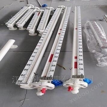
The magnetic steel inside the oil level gauge is transmitted to the on-site indicator through magnetic coupling, and the liquid level or boundary position inside the container is clearly and intuitively indicated by the red and white colors (liquid red and gas white). That is, when the liquid level rises, the indicator changes from white to red, and when the liquid level drops, the indicator changes from red to white. The actual height of the medium liquid (boundary) position inside the container is at the junction of the red and white colors of the indicator. Remote detection and control can also be achieved through optional level transmitters and level switches.
Product Details
Oil level gaugeIt refers to a level gauge without any auxiliary functions (such as heat tracing, frost prevention, etc.), and is also a common and commonly used type of level gauge in our company's magnetic float level gauge series products. Mainly used for measuring the liquid level or boundary position of media in high, medium, and low pressure vessels. If a liquid level alarm switch and a remote transmitter are installed on the instrument, remote control, automatic detection, and recording can be achieved.

The common and commonly used types of liquid level gauges in this series of products. Mainly used for measuring the liquid level or boundary position of media in high, medium, and low pressure vessels. If a liquid level alarm switch and a remote transmitter are installed on the instrument, remote control, automatic detection, and recording can be achieved.
Technical parameters of oil tank level gauge:
Operating pressure: ≤ 32.0MPa
Operating temperature: 0~450℃
Measurement range: 300~6000mm (extra long liquid level gauges can also be made according to user needs, and extra long ones can be segmented due to inconvenient transportation.). )
● Medium density: 0.45~2.0g/cm³(Measurement boundary)
● Medium density difference: ≥ 0.15g/cm3
Accuracy: ± 10mm
● Connection flange standard: HG/T20592-2009 DN20 or customized by the user (various standard flanges such as GB, HGJ, ANSI, SH, DIN, JIS, etc. can be made according to the user's requirements)
Structure and working principle of oil tank level gauge:
1. Basic type
According to the principle of buoyancy, the float moves up and down in the measuring tube with the rise and fall of the liquid level. The magnetic steel inside the float drives the red and white flip columns to flip 180 ° through coupling. When the liquid level rises, the flip column changes from white to red, and when it falls, it changes from red to white, thus achieving liquid level indication.

2. Electric remote transmission
Install a transmitter on the float level gauge, move the float up and down, and use magnetic coupling to sequentially move the measuring elements inside the guide rod to obtain resistance signal changes, convert them into standard signal outputs of 0-10mA or 4-20mA, and connect them with display instruments or computers to achieve remote transmission.
4-20mA remote transmission type installation diagram

3. Upper and lower limit switch output
A controller is installed on the liquid level gauge riser at the upper and lower limit positions set by the user. The controller is equipped with a self holding reed switch, which uses a magnetic float to move with the liquid level to trigger an alarm or limit control when the switch is activated.
Point signal control installation diagram

Conditions for use of oil tank level gauge:
model |
structural type |
Applicable Conditions |
liquid contact material |
Installation type |
||
Operating temperature |
Operating pressure |
medium density |
||||
UHZ - 1 |
Low voltage ordinary type |
0~450 |
≤2.5 |
0.45~2.0 |
stainless steel |
Side/Top Side/Side bottom/top bottom |
UHZ - 2 |
Medium voltage ordinary type |
0~450 |
≤4.0 |
0.45~2.0 |
stainless steel |
Side/Top Side/Side bottom/top bottom |
UHZ - 3 |
High voltage ordinary type |
0~450 |
≤32.0 |
0.6~2.0 |
stainless steel |
Side/Top Side/Side bottom/top bottom |
1. 4-20mA transmission device:

a、 Power supply 220VAC or 24VDC
b、 Output 1-5V 4-20mA
c、 Environmental temperature -40 ℃~+60 ℃
d、 Long distance transmission * 3km (with cable capacitance and inductance * not exceeding 0.04uf.22mH)
e、 Environmental vibration frequency ≤ 25Hz, amplitude ≤ 0.5MM
f、 Load impedance 250 Ω, power consumption<1.0W
g、 Explosion proof flexible joint M20 × 1.5 internal thread (can also be matched according to user requirements)
h、 Explosion proof type, explosion-proof type, explosion-proof intrinsic safety type
2. Point signal:
a、 Power supply: 220V or 24VAC, DC (24VAC or DC)
b、 Output signal: Two normally open and two normally closed switch signals
c、 Environmental temperature: -40 ℃~+60 ℃
d、 Contact capacity: 220VAC 0.25A, 24VDC 0.5A
e、 Environmental vibration frequency ≤ 25Hz, amplitude ≤ 0.5mm
Composition and wiring of oil ball tank level gauge system:
1. Upper and lower limit switch output
Composed of a self retaining reed switch and converter, the reed switch and converter are installed on site and in the control room respectively, with three pairs of contact switches provided by the converter.
2. Electric remote transmission
It consists of two parts: the measuring unit and the transmitting unit.
3. Intrinsic safety explosion-proof
A with intrinsic safety explosion-proof, upper and lower limit switch output type
The explosion-proof switch consists of a reed switch and a safety barrier with relay contacts, which can directly provide users with a pair of normally open or normally closed contacts. If users require more touchpoints, they can place special design orders. (Figure 3)
B-belt security explosive remote transmission type
Suitable for use in π - class electrical equipment (factory use), C-class gas, surface temperature group T4 (135 ℃). (Figure 4)
C Precautions for use
① The transmitter housing is equipped with an external grounding, which must be reliably grounded when used by the user.
② The use of safety barriers should comply with the relevant instructions.
③ The connecting cable between the transmitter and the intrinsic safety end of the safety barrier is a two core shielded cable with a core wire cross-sectional area greater than 0.5m, and the cable allows a distributed capacitance of 0.8 μ F.
Characteristics of oil ball tank level gauge:
1. The design is simple, compact, sturdy, reliable, with a long lifespan, and can be installed and used outdoors for many years without maintenance work;
2. The measuring tube is isolated from the liquid level display part, liquid level transmitter, and alarm switch in terms of pressure resistance and gas resistance;
3. Wide range of working pressure, with pressure resistance ranging from vacuum to 42MPa;
4. Wide working temperature range, suitable for temperatures ranging from -190 to+450 ℃;
5. Widely used for measuring liquid levels that are highly corrosive, flammable, explosive, toxic, highly radioactive, agitated, and contaminated;
6. Each model can be equipped with a passive self holding ON/OFF alarm switch to achieve automatic control or alarm of high and low liquid levels;
7. Each model can be equipped with a 4-20mADC liquid level sensor for remote centralized measurement and control.
8. Explosion proof rating: Complies with Exib Ⅱ CT5 requirements.
Selection diagram of oil tank level gauge:
| UHZ series magnetic flap level gauge | ||||||||
| 1 Side mounted type 2-top installation |
Installation method | |||||||
|
1 PP 2 PVC 3 Stainless Steel 304 4 stainless steel 316L Stainless steel lined with PTFE 6 Other |
Main material | |||||||
| 1 0.6MPa 2 1.6MPa 3 2.5MPa 4 4.0Mpa |
Nominal Pressure | |||||||
| 1 Basic type 2 with upper and lower limit switch output 3 charged remote transmission (0-10mA output, 220V, AC) 4 charged remote transmission (4-20mA output, 24V, DC) 5-belt local security explosive type (4-20mA, 24V, DC) 6 intrinsically safe explosion-proof upper and lower limit switch outputs |
type | |||||||
| Installation spacing (measurement range) | ||||||||
| L1 installation depth (top mounted type (0-4000mm optional) | ||||||||
Medium density ρ (g/c) ) |
||||||||
| UHZ | 2 | 2 | 1 | 1 | L=2500mm | L1=3000mm | ρ=0.8g/c |
for example |
Selection diagram of oil ball tank level gauge:
| UHZ series magnetic flap level gauge | ||||||||
| 1 Side mounted type 2-top installation |
Installation method | |||||||
|
1 PP 2 PVC 3 Stainless Steel 304 4 stainless steel 316L Stainless steel lined with PTFE 6 Other |
Main material | |||||||
| 1 0.6MPa 2 1.6MPa 3 2.5MPa 4 4.0Mpa |
Nominal Pressure | |||||||
| 1 Basic type 2 with upper and lower limit switch output 3 charged remote transmission (0-10mA output, 220V, AC) 4 charged remote transmission (4-20mA output, 24V, DC) 5-belt local security explosive type (4-20mA, 24V, DC) 6 intrinsically safe explosion-proof upper and lower limit switch outputs |
type | |||||||
| Installation spacing (measurement range) | ||||||||
| L1 installation depth (top mounted type (0-4000mm optional) | ||||||||
| Medium density ρ (g/c)) |
||||||||
| UHZ | 2 | 2 | 1 | 1 | L=2500mm | L1=3000mm | ρ=0.8g/c |
for example |
Installation of oil ball tank level gauge:
Firstly, check whether the data on the liquid level gauge label matches the ordering requirements. There should be no magnetism within 500mm of the liquid level gauge, otherwise it will affect the normal operation of the liquid level gauge.
2. A shut-off valve should be installed between the liquid level gauge and the container to cut off materials during maintenance and cleaning. When the measurement range is greater than 4m, support points should be added to the container and connected to the support points on the liquid level gauge for reinforcement. The connection method includes flanges or fittings. The main installation must be vertical with an error of less than 3 degrees.
3. Open the drain flange cover and gently insert the magnetic float, paying attention to the arrow pointing upwards (heavy end facing upwards), and do not install it in reverse. Install the sealing gasket and flange cover, and tighten the screws evenly. Install a shut-off valve and sealing gasket between the liquid level gauge and the container interface flange, and tighten the docking screws evenly.
Selection diagram:
| UHZ series magnetic flap level gauge | ||||||||
| 1 Side mounted type 2-top installation |
Installation method | |||||||
|
1 PP 2 PVC 3 Stainless Steel 304 4 stainless steel 316L Stainless steel lined with PTFE 6 Other |
Main material | |||||||
| 1 0.6MPa 2 1.6MPa 3 2.5MPa 4 4.0Mpa |
Nominal Pressure | |||||||
| 1 Basic type 2 with upper and lower limit switch output 3 charged remote transmission (0-10mA output, 220V, AC) 4 charged remote transmission (4-20mA output, 24V, DC) 5-belt local security explosive type (4-20mA, 24V, DC) 6 intrinsically safe explosion-proof upper and lower limit switch outputs |
type | |||||||
| Installation spacing (measurement range) | ||||||||
| L1 installation depth (top mounted type (0-4000mm optional) | ||||||||
| Medium density ρ (g/c)) |
||||||||
| UHZ | 2 | 2 | 1 | 1 | L=2500mm | L1=3000mm | ρ=0.8g/c |
for example |
Installation of oil ball tank level gauge:
Firstly, check whether the data on the liquid level gauge label matches the ordering requirements. There should be no magnetism within 500mm of the liquid level gauge, otherwise it will affect the normal operation of the liquid level gauge.
2. A shut-off valve should be installed between the liquid level gauge and the container to cut off materials during maintenance and cleaning. When the measurement range is greater than 4m, support points should be added to the container and connected to the support points on the liquid level gauge for reinforcement. The connection method includes flanges or fittings. The main installation must be vertical with an error of less than 3 degrees.
3. Open the drain flange cover and gently insert the magnetic float, paying attention to the arrow pointing upwards (heavy end facing upwards), and do not install it in reverse. Install the sealing gasket and flange cover, and tighten the screws evenly. Install a shut-off valve and sealing gasket between the liquid level gauge and the container interface flange, and tighten the docking screws evenly.
Installation:
Firstly, check whether the data on the liquid level gauge label matches the ordering requirements. There should be no magnetism within 500mm of the liquid level gauge, otherwise it will affect the normal operation of the liquid level gauge.
2. A shut-off valve should be installed between the liquid level gauge and the container to cut off materials during maintenance and cleaning. When the measurement range is greater than 4m, support points should be added to the container and connected to the support points on the liquid level gauge for reinforcement. The connection method includes flanges or fittings. The main installation must be vertical with an error of less than 3 degrees.
3. Open the drain flange cover and gently insert the magnetic float, paying attention to the arrow pointing upwards (heavy end facing upwards), and do not install it in reverse. Install the sealing gasket and flange cover, and tighten the screws evenly. Install a shut-off valve and sealing gasket between the liquid level gauge and the container interface flange, and tighten the docking screws evenly.
Selection diagram:
| UHZ series magnetic flap level gauge | ||||||||
| 1 Side mounted type 2-top installation |
Installation method | |||||||
|
1 PP 2 PVC 3 Stainless Steel 304 4 stainless steel 316L Stainless steel lined with PTFE 6 Other |
Main material | |||||||
| 1 0.6MPa 2 1.6MPa 3 2.5MPa 4 4.0Mpa |
Nominal Pressure | |||||||
| 1 Basic type 2 with upper and lower limit switch output 3 charged remote transmission (0-10mA output, 220V, AC) 4 charged remote transmission (4-20mA output, 24V, DC) 5-belt local security explosive type (4-20mA, 24V, DC) 6 intrinsically safe explosion-proof upper and lower limit switch outputs |
type | |||||||
| Installation spacing (measurement range) | ||||||||
| L1 installation depth (top mounted type (0-4000mm optional) | ||||||||
| Medium density ρ (g/c)) |
||||||||
| UHZ | 2 | 2 | 1 | 1 | L=2500mm | L1=3000mm | ρ=0.8g/c |
for example |
Installation of oil ball tank level gauge:
Firstly, check whether the data on the liquid level gauge label matches the ordering requirements. There should be no magnetism within 500mm of the liquid level gauge, otherwise it will affect the normal operation of the liquid level gauge.
2. A shut-off valve should be installed between the liquid level gauge and the container to cut off materials during maintenance and cleaning. When the measurement range is greater than 4m, support points should be added to the container and connected to the support points on the liquid level gauge for reinforcement. The connection method includes flanges or fittings. The main installation must be vertical with an error of less than 3 degrees.
3. Open the drain flange cover and gently insert the magnetic float, paying attention to the arrow pointing upwards (heavy end facing upwards), and do not install it in reverse. Install the sealing gasket and flange cover, and tighten the screws evenly. Install a shut-off valve and sealing gasket between the liquid level gauge and the container interface flange, and tighten the docking screws evenly.

Oil level gaugeprice