-
E-mail
273729235@qq.com
-
Phone
15896194586
-
Address
Jinhu Industrial Park, Jiangsu Province
Product Categories
Jiangsu Yushun Instrument Co., Ltd


Distilled water level gauge
NegotiableUpdate on 01/23
- Model
- Nature of the Manufacturer
- Producers
- Product Category
- Place of Origin
Overview
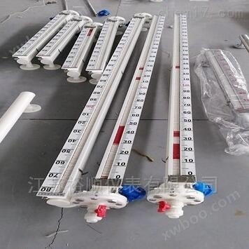
The magnetic steel in the distilled water level gauge is transmitted to the on-site indicator through magnetic coupling, and the liquid level or boundary position in the container is clearly and intuitively indicated by the red and white colors (liquid red and gas white). That is, when the liquid level rises, the indicator changes from white to red, and when the liquid level drops, the indicator changes from red to white. The actual height of the medium liquid (boundary) position in the container is at the red and white boundary of the indicator. Remote detection and control can also be achieved through optional level transmitters and level switches.
Product Details
Distilled water level gaugeThe top mounted magnetic flap level gauge series products generally use DN80 or DN100 connection flanges, while the side mounted magnetic flap level gauge uses three connection methods: flange connection (such as DN25), clamp connection, and threaded connection.

The segmented installation of this level gauge can be done in two ways: one is staggered installation, and the other is flange connection installation. Both of these methods have their own advantages and disadvantages. The staggered installation is shown in Figure 1. This installation method has overlapping parts between two parallel and staggered magnetic flap level gauges, which can ensure that the displayed liquid level values are continuous. The disadvantage is that the cost is relatively high.
The obvious advantages of the distilled water storage tank level gauge are:
This level gauge has a direct reading feature for on-site display. No need for multiple sets of liquid level gauges to be combined. It has the advantages of single unit full range measurement, equipment with fewer openings, clear display, prominent markings, and intuitive readings. Due to its magnetic coupling isolator enclosed structure. Especially suitable for detecting flammable, explosive, corrosive and toxic liquid levels. Thus, the liquid level detection method in the original complex environment becomes simple, reliable, and safe.
The technical parameters that need to be understood and provided before selecting and ordering the level gauge for distilled water storage tanks are:
1. Installation method: Side mounted, top mounted
2. Measurement media: such as water, oil, other chemical solvents, and liquid raw materials
3. Material requirements: such as 304 stainless steel, 316L stainless steel, stainless steel lined with PTFE, PP, PVC (if the user is not clear, after providing relevant parameters, our technical personnel can help choose the location)
4. Measuring medium temperature: The different temperatures determine the different material types for the float and display panel. When the temperature is too low in winter, it is necessary to install a potential heat or steam jacket for insulation. The liquid level gauge can measure the medium temperature of -20 ℃~500 ℃.
5. Work pressure: The magnitude of the pressure determines the thickness of the main pipe and the differences in welding and other processing techniques.
Table 1 Selection of Tank Level Gauge:
Basic type | |
Measurement range (i.e. installation flange center distance) | |
500, 800, 1600, 1400, 1700, 2500, 4000, 6000, 1000; | |
On site indication accuracy: |
±mm |
Operating Temperature |
-196℃~200℃ |
Medium density difference: |
≥ 0.15g/cm3 (measurement boundary) |
Medium density: |
≥ 0.45g/cm3 (measurement boundary) |
Medium wave stability: |
≤1st(10-4m2/s) |
Logic diagram for liquid level calculation
On the basis of database modification, the distance between the intersection of LT-2 liquid phase port c and LT-1 liquid phase port b is 0.5m. When the LT-1 liquid level gauge actually reaches point c, which is 1.45m (43%), the LT-1 signal of the liquid level gauge does not output and switches to the LT-2 signal for display. In the program, a constant of 43% (lower liquid level height) should be added to the LT-2 display value to display the final actual liquid level.

System performance testing
Through practical use in the production process, the liquid level gauge has achieved significant accuracy in measurement. After program calculation, the error of the liquid level display value is controlled at 1%, and the output display value runs stably without any abnormal faults. This calculation method not only reduces the tedious calculation process for operators, but also is more suitable for liquid level measurement with control circuits.
Working principle of liquid level gauge:
When the sensor of the magnetostrictive liquid level gauge is working, the circuit part of the sensor will excite a pulse current on the waveguide wire. When the current propagates along the waveguide wire, a pulse current magnetic field will be generated around the waveguide wire. A float is installed outside the measuring rod of the magnetostrictive liquid level gauge, which can move up and down along the measuring rod with the change of liquid level. There is a set of magnetic rings inside the float. When the pulse current magnetic field meets the magnetic ring magnetic field generated by the float, the magnetic field around the float changes, causing the waveguide wire made of magnetostrictive material to generate a torsional wave pulse at the position of the float. This pulse is transmitted back along the waveguide wire at a fixed speed and detected by the detection mechanism. The position of the float, i.e. the liquid level, can be determined by measuring the time difference between the pulse current and the torsional wave.

When the gravity of the magnetic flip plate is greater than its adhesion to the pipe wall, the magnetic flip plate sinks to the buffer spring with the discharge liquid. During the actual disassembly and inspection process, it was found that due to the small elasticity of some manufacturers' buffer springs or the large diameter of cylindrical springs, under the action of pressure difference, the magnetic flip plate descends and compresses the spring, and its lower end face directly drops to the discharge outlet. Due to the semi-circular structure at both ends of the magnetic flap and the circular discharge port inside the flange, a relatively tight contact is formed at the contact point between the two. In addition, the sealing effect of the viscous substance settling at the bottom of the main pipe causes the lower end of the magnetic flap to face the discharge port, forming a blockage. The magnetic flap itself is compressed against the discharge port by the residual pressure inside the main pipe.
Instrument leakage occurs
1. Reason for malfunction: The sealing part is not sealed properly. Troubleshooting method: Press the cover tightly. 2. Cause of malfunction: Damaged seal. Troubleshooting method: Replace the sealing gasket. 3. Cause of malfunction: Weld seam cracking. Troubleshooting method: Repair welding or send to the manufacturer for repair.
Distilled water storage tank level gaugeConsidering the wiring of the liquid level gauge:
Errors can result in inaccurate measurements at the slightest level and damage to the instrument at the most severe. Therefore, when wiring the magnetic flap level gauge, the following points must be noted:
1. When wiring, avoid large capacity transformers, motors, or interference sources;
2. For explosion-proof types, wiring must be carried out in accordance with relevant regulations to ensure explosion-proof performance;
3. Unscrew the terminal cover of the junction box, thread the cable through the cable connector, and connect it to both ends of 24VDC;
4. Connect the grounding terminal as needed;
5. Tighten the terminal cover of the junction box.
6. For explosion-proof instruments, wiring must be carried out in accordance with relevant regulations to ensure explosion-proof performance;
There are many materials for remote magnetic flap level gauges, which are used for different measuring media; Moreover, the digital display meter can also trigger an alarm. There are two wire, three wire, and four wire remote transmission connections. If the magnetic flap level gauge uses a four wire system, the positive and negative power supply of the magnetic flap level gauge will be connected to the positive and negative power supply. Connect the positive and negative terminals of the 4-20mA input of the instrument separately. If a safety barrier is used, the positive and negative input terminals of the 24V safety barrier power supply correspond to the positive and negative terminals of the magnetic flap level gauge, and the positive and negative output terminals of the power supply correspond to the positive and negative terminals of the instrument.
Table 2 Selection of Tank Level Gauge:
Installation form and content of magnetic flap level gauge |
side-mounted |
Installation spacing (measurement range) |
500,800,1100,1400,1700,2000,2500,3000mm |
work pressure |
0.6,1.6,2.5,4.0MPa |
medium density |
≥ 0.76g/cm 3 |
medium temperature |
-40 ℃ ~100 ℃ |
ambient temperature |
-40 ℃ ~+70 ℃ |
indication error |
± 10mm |
medium viscosity |
≤ 1st(10 - 4 m/s) |
Upper and lower limit switch output |
1. Control sensitivity: 10mm |
Continuous display of electric remote transmission |
1. Accuracy: ± 1.5% |
How to solve the problem of medium affecting the float operation with a liquid level gauge:
If there is sediment in the body of the liquid level gauge after use, it will affect the normal operation of the float and must be cleaned regularly. Before cleaning, first close the gas-liquid phase valve to remove any remaining substances from the cylinder. After cleaning, assemble the float as it is and switch it upside down. The sealing gasket should be replaced to prevent aging, leakage, and tighten the screws.

Distilled water level gaugeprice