-
E-mail
shengkangdianqi@163.com
-
Phone
13792162101
-
Address
Building A, High tech Entrepreneurship Center, Zibo High tech Development Zone
Product Categories
- Flash evaporator
- Oxidation stability tester
- Reactive power compensation controller
- Intelligent three-way synchronous switch
- power capacitor
- Intelligent low-voltage branch monitoring terminal
- Intelligent distribution transformer monitoring terminal
- Open and closed flash point tester
- Micro moisture analyzer
Shandong Shengkang Electric Co., Ltd

Low voltage branch monitoring terminal
NegotiableUpdate on 01/21
- Model
- Nature of the Manufacturer
- Producers
- Product Category
- Place of Origin
Overview
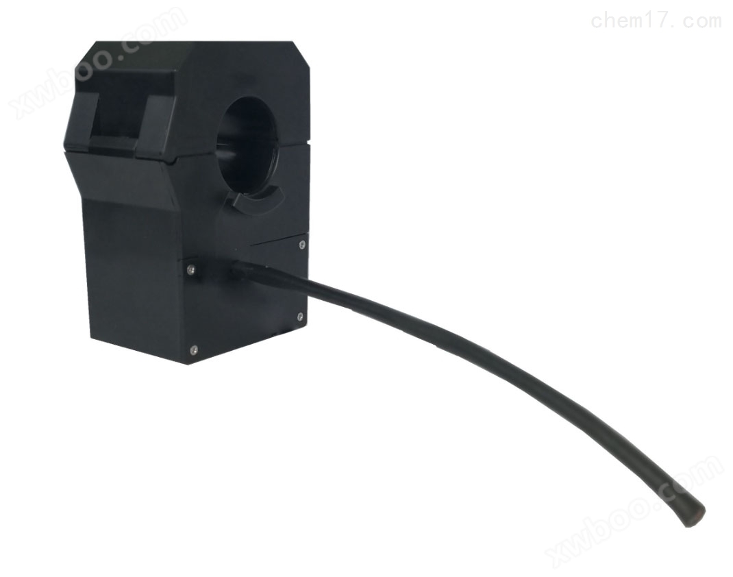
SCPB-ILTU low-voltage branch monitoring terminal is suitable for power monitoring and fault detection of 400V lines. Installed on 400V branch lines in low-voltage distribution network box type substations, residential distribution rooms, column mounted transformers, etc. according to phase, it realizes the monitoring of the operation status of low-voltage 400V branch lines and the indication of line fault status, measures current, voltage, cable temperature and other information, and calculates active and reactive power. Equipped with an independent fault current transformer, it monitors line faults and alarms.
Product Details
1 SCPB-ILTULow voltage branch monitoring terminalOverview
Suitable for power monitoring and fault detection on 400V lines. Installed on 400V branch lines in low-voltage distribution network box type substations, residential distribution rooms, column mounted transformers, etc. according to phase, it realizes the monitoring of the operation status of low-voltage 400V branch lines and the indication of line fault status, measures current, voltage, cable temperature and other information, and calculates active and reactive power. Equipped with an independent fault current transformer, it monitors line faults and alarms.
2 SCPB-ILTULow voltage branch monitoring terminalFeatures
2.1 Integrated, low-power, with high reliability and adaptability.
2.2 Simultaneously meet the regulatory and safety requirements for indoor and outdoor on-site installation.
2.3 Adopting a retractable structure and equipped with locking components, it is easy to install and firm.
Unit 2.4 is manufactured using thermosetting resin materials through casting and curing processes. The iron core opening is sealed with a thermosetting outdoor silicone rubber sealing ring, which is waterproof and dustproof.
2.5 It has the function of measuring the load current and phase voltage of the circuit, and calculating the phase active power and phase reactive power.
2.6 Using a Roche coil as a protective current transformer, through integrator, A/D conversion, and calculation processing, it can quickly respond to the fault current of the line and achieve the function of line fault detection.
2.7 It has a phase fault indication function to protect the fundamental component of the current as the input for fault discrimination. After the fault indication action, the state remains until it returns.
2.8 Equipped with pressure/no pressure detection function.
2.9 Equipped with temperature detection function
2.10 Equipped with RS485 interface for debugging free communication function, the communication interface is electrically isolated from phase voltage input, working power supply, etc. Communication protocol based on Modbus.
2.11 has a 64 bit device identifier.
2.12 has the function of setting parameters such as channel coefficient and phase fault indication action value.
2.13 Unit interface and indication
a) Working power interface;
b) 1 RS485 communication interface;
c) Phase voltage and ground input interface;
d) Indicator light: equipped with unit operation status and phase fault status indication.
e) Button: equipped with unit operation mode and fault indication reset button.
3 Technical parameters
3.1 Environmental conditions
3.1.1 Environmental temperature and humidity
The unit meets the C3 level requirements, and the temperature and humidity classification of the workplace environment is shown in Table 1.
Table 1 Classification of Workplace Environment Temperature and Humidity
level |
ambient temperature |
Humidity |
Usage location |
||
Range ℃ |
Large change rate ℃/min |
relative humidity % |
High humidity g/m3 |
||
C1 |
-5~+45 |
0.5 |
5~95 |
29 |
Not yet* |
C2 |
-25~+55 |
0.5 |
10~100 |
29 |
indoor |
C3 |
-40~+70 |
1.0 |
10~100 |
35 |
Sheltering places, outdoors |
CX |
Specific (to be determined through consultation between the user and the manufacturer as needed) |
||||
3.1.2 Altitude
The altitude of the installation site should not exceed 1000m.
3.1.3 Operating Environment
a) No explosion hazard, no corrosive gases or conductive dust, no severe mold presence, and no sources of severe vibration and shock.
b) The use of ambient air may be exposed to sunlight and ultraviolet radiation;
c) The electromagnetic environment of the usage location does not exceed the electromagnetic compatibility parameter requirements of this product;
d) The usage environment should not exceed the vibration and impact specified for this product;
e) Reliable connection to the grounding grid.
3.2 Rated Parameters
3.2.1 Analog Input
a) Rated AC voltage: 220V;
b) Rated AC current:
Protective AC current transformer: 400A
AC current transformer for measurement: 600A
c) Rated frequency: 50Hz.
3.2.2 Technical parameters of DC power supply
a) Rated voltage: 24V DC;
b) Allowable deviation: -10% to+10%;
c) Ripple factor: ≤ 5%.
3.2.3 Power consumption
a) DC power supply circuit: The overall power consumption of the machine shall not exceed 1W;
b) AC voltage circuit: At rated input, the power consumption of each circuit is less than 0.5VA.
3.3 Measurement Parameters
a) Current and voltage errors: ≤ 0.5%, measurement range 0-120%;
b) Active and reactive power errors: ≤ 1.0%, measurement range 0-120%;
c) Measurement error of protective current: ≤ 8%, measurement range 0-10In;
d) Temperature measurement error: ≤ 2 ℃, measurement range -20~60 ℃.
3.4 Overload Capacity
a) Protective AC current circuit:
1) 2 times the rated current, continuous operation;
2) 10 times the rated current, allowing for 10 seconds.
b) AC current circuit for measurement:
1) 1.2 times the rated current, continuous operation;
2) 10 times the rated current, allowing for 1 second.
c) AC voltage circuit:
1) 1.2 times rated voltage, continuous operation;
2) 1.4 times the rated voltage, allowing for 1Os.
3.5 Protection Action
a) Operating current setting range: 400A -3600A (10% -90 times the rated value)
b) Action current establishment time: 20ms
b) Action delay time setting range: 20ms-500ms
c) Action time resolution:<2ms
3.6 Reliability
The average working time (MTBF) shall not be less than 30000 hours.
4 Appearance structure
The shell structure adopts insulated and flame-retardant engineering plastics, and the protection level meets the requirements of IP67 specified in GB/T 4208;
All exposed metal fasteners at the opening of the iron core are made of corrosion-resistant stainless steel material.
The structure and dimensions of the intelligent low-voltage branch monitoring unit are shown in Figure 1.

Figure 1 Schematic diagram of the structure of the intelligent low-voltage branch monitoring unit
5 Safety regulations and electromagnetic compatibility
5.1 Insulation resistance
Under normal atmospheric conditions, the insulation resistance between the charged and non charged parts of the unit and the casing, as well as between electrically unrelated circuits, shall be measured using a megohmmeter with an open circuit voltage of 500V DC, and shall not be less than 5M Ω.
5.2 Insulation strength
Table 2 Insulation Strength
Rated insulation voltage Ui (V) |
Effective value of test voltage (V) |
Ui≤60 |
500 |
60<Ui≤125 |
1000 |
125<Ui≤250 |
2000 |
5.3 Electromagnetic compatibility performance
Meet the electromagnetic compatibility test requirements specified in GB/T 14598.26 for the following items:
5.3.1 Ability to resist fast transient pulse group interference
Table 3 Main parameters of fast transients
Test Project |
Test circuit |
Test standards |
fast transient |
power circuit |
6.2 of GB/T 14598.26 (Table 4.2 Class B) |
communication port |
6.3 in GB/T 14598.26 (Table 5.2 Class B) |
|
signal loop |
6.4 in GB/T 14598.26 (Table 6.2 Class B) |
5.3.2 Ability to resist damped oscillatory waves
Table 4 Main Parameters of Damping Oscillatory Waves
Test Project |
Test circuit |
Test standards |
Damped oscillation wave |
power circuit |
6.2 (Table 4.3) in GB/T 14598.26 |
communication port |
6.3 in GB/T 14598.26 (Table 5.3) |
|
signal loop |
6.4 (Table 6.3) in GB/T 14598.26 |
5.3.3 Ability to resist surge interference
Table 5 Main parameters of surge test
Test Project |
Test circuit |
Test standards |
surge |
power circuit |
6.2 of GB/T 14598.26 (Table 4.4, Class B-3) |
communication port |
6.3 of GB/T 14598.26 (Table 5.4 B-class - Level 2) |
|
signal loop |
6.4 in GB/T 14598.26 (Table 6.4 B-class - Level 3) |
5.3.4 Ability to resist electrostatic discharge
Table 6 Main parameters of electrostatic discharge test
Experimental project |
Types |
Test standards |
Electrostatic Discharge |
Contact, air |
6.1 in GB/T 14598.26 (Table 3.2-3 Level) |
Note: The test level is the corresponding level in the table of the standard, arranged from low to high. | ||
5.3.5 Ability to resist power frequency magnetic fields
Table 7 Main Parameters of Power Frequency Magnetic Field Test
Experimental project |
Waveform |
Test standards |
power frequency magnetic field |
Continuous sine wave |
6.1 of GB/T 14598.26 (Table 3.3) |
Similar Product Recommend