-
E-mail
997037929@qq.com
-
Phone
13306184099
-
Address
No. 119-120, Building 104, Wuzhou Industrial Expo City, 299 Jincheng East Road, Xinwu District, Wuxi City
Product Categories
Wuxi Kaiweilian Hydraulic Machinery Co., Ltd


GLL2-6,GLL2-7,GLL3-8, Tubular cooler
NegotiableUpdate on 01/22
- Model
- Nature of the Manufacturer
- Producers
- Product Category
- Place of Origin
Overview
GLL2-6,GLL2-7,GLL3-8, The tube type cooler and GL tube type oil cooler use low ribbed finned copper tubes as the heat exchange tube material, and adopt manufacturing processes such as transverse baffle plates, longitudinal turbulence plate structures, and mechanical expansion tubes. Therefore, they have the advantages of novel structure, small volume, light weight, and heat transfer. Mainly used in low viscosity hydraulic and lubrication systems to cool working oil to a specified temperature, it is widely applicable for cooling various hydraulic equipment in industries such as chemical, power, metallurgy, mining, and light industry. It is an ideal cooling device.
Product Details
GLL2-6,GLL2-7,GLL3-8, 列管式冷却器,The material of the heat exchange tube of GL tube type oil cooler adopts low ribbed finned copper tube, and adopts manufacturing processes such as transverse baffle plate, longitudinal turbulence plate structure, and mechanical expansion tube. Therefore, it has the advantages of novel structure, small volume, light weight, and heat exchange. Mainly used in low viscosity hydraulic and lubrication systems to cool working oil to a specified temperature, it is widely applicable for cooling various hydraulic equipment in industries such as chemical, power, metallurgy, mining, and light industry. It is an ideal cooling device.
Working principle of tubular cooler
Manual working process: After the water filter is connected to the pipeline system, water enters the filter through the lower inlet. When impurities in the water pass through the mesh core, they are trapped on the mesh core due to their larger volume than the mesh core holes. When they accumulate to a certain amount, it causes a certain pressure difference between the inlet and outlet. (The precision and diameter of the filter screen vary, and the pressure difference is generally 0.15Mpa.) Manually open the drain valve to start draining. Rotate the handle clockwise or counterclockwise every 10-30 seconds. Rotate one step and fix the handle to each concave part. The water flow will reverse wash the impurities and dirt attached to the inner wall of the mesh core. Rotate once, close the drain valve, and manually drain the water.
1. Differential pressure discharge: When impurities accumulate to a certain amount, the differential pressure signal between the cooling water inlet and outlet pipes is used to backwash the discharge. That is, the electric contact pressure gauge is connected to the control signal, and the control mechanism opens the electric discharge valve. The electric reducer will operate at a speed of 3-6 revolutions per minute, and the water flow will reverse wash the impurities and pollutants attached to the inner wall of the mesh core. They will be discharged into the cooling water outlet pipe through the discharge pipeline and discharge valve, and the cleaning time is about 5-10 minutes. When large debris appears and the filter cannot operate properly, the electric device should run in the opposite direction to flush the debris.
Coolers, cooler prices, cooler manufacturers
Wuxi Kaiweilian Hydraulic mainly produces: hydraulic valves, hydraulic pumps, high-pressure ball valves, accumulators, safety valve groups, hydraulic coolers, filters, power-off brakes, electromagnetic brakes, and lubrication systems
Installation size
| ||||||||||||||||||||||||||||||||||||||||||||||||||||||||||||||||||||||||||||||||||||||||||||||||||||||||||||||||||||||||||||||||||||||||||||||||||||||||||||||||||||||||||||||||||||||||||||||||||||||||||||||||||||||||||||||||||||||||||||||||||||||||||||||||||||||||||||||||||||||||||||||||||||||||||||||||||||||||||||||||||||||||||||||||||||||||||||||||||||||||||||||||||||||||||||||||||||||||||||||||||||||||||||||||||||||||||||||||||||||||||||||||||||||||||||||||||||||||||||||||||||||||||||||||||||||||||||||||||||||||||||||||||||||||||||||||||
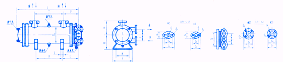
Before starting, check all accessories and instruments and ensure that all connections are tight |
Model Description: The GL tube type oil cooler heat exchange tube material adopts low ribbed finned copper tube, and adopts manufacturing processes such as transverse baffle plate, longitudinal turbulence plate structure, and mechanical expansion tube. Therefore, it has the advantages of novel structure, small volume, light weight, and heat exchange. 2LQFW type tubular cooler can be customized non-standard. Using low ribbed finned copper tubes, and employing manufacturing processes such as transverse baffle plates, longitudinal turbulent plate structures, and mechanical expansion tubes, it has the advantages of novel structure, small volume, light weight, and heat transfer. The tube type cooler adopts a dual structure, consisting of two oil coolers of the same area and a three-way valve device, one working and the other standby. Each tube type cooler can bear the cooling load of the entire system. One end of the tube plate is fixed, and the other end is a floating, detachable tube bundle and water chamber cover, which is easy to clean, inspect and maintain during operation. The material of the tubular cooler can be selected from various options based on the usage location and water system conditions.GLL2-6,GLL2-7,GLL3-8, 列管式冷却器, |
The technical problem to be solved by this utility model is to provide a tube type oil cooler with better cooling effect. The technical solution of the present utility model is to provide a tubular oil cooler with the following structure: a left end cover, a right end cover, a housing provided with an oil inlet and an oil outlet, multiple baffle plates staggered and installed in the housing to allow hydraulic oil to flow in a tortuous manner, and a heat exchange component installed in the inner cavity of the housing through two fixed plates. The heat exchange component includes an inlet component and an outlet component, both of which are composed of several heat exchange tubes arranged along the axial direction of the housing. The two fixed plates are respectively connected to the left and right ends of the housing, and the left and right end covers are located on the left and right sides of the housing and connected to the fixed plate. The right end cover is provided with an inlet. The outlet is connected to the inlet component, and the inlet is connected to the inlet component. The outlet is connected to the outlet component, and a sleeve is tightly fitted on the outer wall of the heat exchange tube, A spiral heat exchanger is installed on the outer wall of the sleeve. The tubular oil cooler described in this utility model, wherein several axial heat dissipation fins can be uniformly distributed on the outer peripheral wall of the shell. The tubular oil cooler described in this utility model, wherein the shell can be made of aluminum alloy material. After adopting the above structure, compared with the existing technology, the tubular oil cooler of this utility model has the following advantages: the outer surface of the heat exchange tube is relatively smooth compared to the existing technology, resulting in a smaller heat exchange area between the heat exchange tube and the hydraulic oil. The spiral heat exchange fins set on the sleeve of the tubular oil cooler of this utility model greatly increase the heat exchange area between the heat exchange tube and the hydraulic oil, thereby improving the cooling effect of the tubular oil cooler of this utility model on the hydraulic oil in the hydraulic pipeline. The appearance and structure of the tubular cooling system are shown in Figure 2, consisting of multiple cooling water pipes, water side end cover plates and cylinders, as well as sealing gaskets and other components. The inside and outside of the cooling water pipe are sealed and separated. The cooling water flows from inside the pipe, while the hot oil flows from outside the pipe and undergoes heat exchange through the pipe wall to cool down the hot oil before flowing out from the outlet.
1、 Usage conditions
The dual cooler is designed and manufactured according to GB151 standards and with reference to West German AD and American TEMA standards. It is made of all steel and partially brass structure, with an oil side working pressure of 1.6MPa, a working temperature of 150 ℃, a water side working pressure of 1.0MPa, and a working temperature of 100 ℃. The product has the advantages of energy saving, high efficiency, safety and reliability; Suitable for oil cooling systems in steam turbine generator sets, compressor sets, fans, pump sets, and the petrochemical industry, and can also be used in other oil cooling systems.
2、 Characteristics
1. The data in the table is for a two process tubular dual oil cooler. If necessary, a four process, six process, bare tube or finned cooling tube cooler can be selected.
2. The installation of the cooler is usually horizontal. If the user needs it, two vertical arrangements can be used, one with the inlet chamber at the bottom and the other with the inlet chamber at the top, which is convenient for disassembling the tube bundle.
3. The standard for oil-water interface flanges shall comply with JB/T81-94, and non-standard flanges shall meet the piping requirements according to user requirements.
4. According to the AP Ⅰ 614 standard, the cooler adopts a dual structure, consisting of two equally sized coolers and a three-way valve device, one working and one standby. Each cooler can withstand the cooling load of the entire system. One end of the tube plate is fixed and the other end is floating. The detachable tube bundle and water chamber cover are convenient for cleaning, inspection, and maintenance during operation. The material of the cooler can be selected according to the usage location and water system conditions. The water chamber, shell, and three-way valve can be made of carbon steel or all stainless steel, and the tube plate can be made of carbon steel, stainless steel, or brass plate; The pipe materials can be selected from ordinary brass tube H68, arsenic brass tube HSn70-1A, aluminum brass tube HA177-2A, stainless steel tube 1Cr18Ni9Ti, B10, B30, etc.
5. The three-way valve adopts a steel welded structure continuous flow conversion valve. This type of valve will not cause interruption of the oil circuit during internal structural failure or valve switching
GLL2-6,GLL2-7,GLL3-8, 列管式冷却器,Manufacturer of plate oil cooler