-
E-mail
2534706874@qq.com
-
Phone
18917076850
-
Address
Room C1, 27th Floor, Science and Technology Capital East Building, Beijing East Road, Huangpu District, Shanghai
Product Categories
Shanghai Yingzhe Industrial Automation Equipment Co., Ltd
Electrical signal transfer of German P+F rotary encoder
NegotiableUpdate on 05/01
- Model
- Nature of the Manufacturer
- Producers
- Product Category
- Place of Origin
Overview
Electrical signal conversion of German P+F rotary encoder: P+F rotary encoder can convert mechanical input into electrical signals, which can be processed through counters, tachometers, programmable logic controllers (such as PLCs), and industrial computers. In the field of industrial automation, P+F rotary encoders can be used to measure angles, positions, velocities, and angular velocities. By using gears, measuring wheels, and constant force opening instruments, we can measure the motion position of a straight line.
Product Details
GermanyP+F rotary encoderElectrical signal conversion: P+F rotary encoder can convert mechanical input into electrical signals, which can be processed through counters, tachometers, programmable logic controllers (such as PLCs), and industrial computers. In the field of industrial automation, P+F rotary encoders can be used to measure angles, positions, velocities, and angular velocities. By using gears, measuring wheels, and constant force opening instruments, we can measure the motion position of a straight line.
P+F rotary encoder
The P+F rotary encoder can be used to measure rotational speed, acceleration, position, and direction. P+F encoders can be applied in a wide range of mechanical engineering industries, such as material handling, logistics, and packaging. You will definitely be able to find products that are suitable for your application environment from our extensive product line.
A Brief Introduction to P+F Optoelectronic Encoder
P+F photoelectric encoder is a sensor that uses the principle of grating diffraction to achieve displacement digital conversion. Through photoelectric conversion, the mechanical geometric displacement on the output shaft is converted into a pulse digital quantity.
The common P+F photoelectric encoder consists of a grating disk, a light-emitting element, and a photosensitive element. A grating is actually a disk engraved with regular transparent and opaque lines. The light flux received by the photosensitive element changes synchronously with the transparent lines, and the output waveform of the photosensitive element is shaped into a pulse signal. Each revolution outputs a pulse. Based on the variation of the pulse, the displacement of the equipment can be accurately measured and controlled.
According to the detection principle, encoders can be divided into optical, magnetic, inductive, and capacitive types. According to its calibration method and signal output form, it can be divided into three types: incremental, linear, and hybrid.
The P+F incremental encoder directly utilizes the principle of photoelectric conversion to output three sets of square wave pulses A, B, and Z phases; A. B has a phase difference of 90 between the two sets of pulses, making it easy to determine the direction of rotation, while Z has one pulse per rotation for reference point positioning. GermanyP+F rotary encoderElectrical signal transfer; Its advantages are simple principle construction, mechanical average life can be over tens of thousands of hours, strong resistance, high reliability, and suitable for long-distance transmission. Its disadvantage is that it cannot output the position information of the shaft rotation.
The P+F encoder is a sensor that directly outputs digital signals. It has several concentric code tracks along the radial direction on its circular code disk, each track consisting of alternating transparent and opaque sector areas. The number of sectors on adjacent code tracks is double the number of digits on the code disk. One side of the code disk is the light source, and the other side corresponds to each code track with a photosensitive element; When the encoder is in different positions, each photosensitive element converts into corresponding level signals based on whether it is illuminated or not, forming binary numbers. The characteristic of this encoder is that it does not require a counter, and a fixed digital code corresponding to the position can be read at any position of the shaft. Obviously, the more code channels there are, the higher the resolution. For an encoder with N-bit binary resolution, its code disk must have N code channels.
The P+F encoder utilizes natural binary or cyclic binary (Gray code) methods for photoelectric conversion. The difference between a linear encoder and an incremental encoder lies in the transparent and opaque line graphics on the disc. The encoder can have multiple encodings and detect the position based on the encoding read from the encoder disc. The design of encoding can use binary code, cyclic code, binary complement code, etc. Its characteristics are:
1. Can directly read the value of angle coordinates;
2. No cumulative error;
3. The position information will not be lost after the power is cut off. However, the resolution is determined by the number of binary bits, which means the accuracy depends on the number of bits. Currently, there are various types such as 10 bits, 14 bits, etc.
A hybrid value encoder that outputs two sets of information: one set of information is used to detect the position of magnetic poles and has information function; The other group has the same output information as the incremental encoder.
P+F photoelectric encoder is an angle (angular velocity) detection device that converts the angle input to the shaft into corresponding electrical pulses or digital quantities using the principle of photoelectric conversion. It has the advantages of small size, high accuracy, reliable operation, and digital interface. It is widely used in devices and equipment that require angle detection, such as CNC machine tools, rotary tables, servo drives, robots, radars, and military target determination.
2、 Implementation of crane correction
1. Implementation of downward correction (correction of large vehicle operation)
In order to improve the measurement and control accuracy of the large vehicle, a detection wheel with a diameter of 600mm can be installed on each of the rigid and flexible legs in the control scheme. A single circle value encoder can also be installed on the detection wheel, and its signal can be read, converted, calculated, and controlled by the PLC for deviation adjustment. This scheme has high measurement accuracy and is not afraid of power failure.
The implementation of downward correction can be divided into two situations: manual correction and automatic correction. When the measurement and calculation error of the rigid retreat and leg rubbing encoder is within ± 3% S (span length S), the PLC calculates and automatically corrects it in real time.
When the measurement and calculation error of the leg rubbing encoder is greater than ± 3% S (with a span length of S), the PLC will automatically stop the large vehicle running mechanism and issue an alarm signal through real-time calculation. At this point, the driver is the operator who can independently operate the just back movement (or leg massage movement) based on the information displayed on the touch screen until the alarm signal is eliminated.
2. Implementation of upward correction
In order to further improve the precise control and correction of the operating mechanism, large-span cranes generally adopt synchronous execution of upper and lower correction. This is to achieve more accurate correction control and prevent mechanical damage or even major accidents caused by the failure of a correction system.
In order to improve the reliability and safety of the operation of the double main beam gantry crane and prevent excessive rotation angle of the flexible hinge support from causing damage to the steel structure, it is necessary to measure the rotation angle of the hinge support in real time, determine whether the rotation angle at each moment is within the allowable range (usually only allowing the distance difference between the walking distance of the steel leg and the flexible leg to be within ± 3 ‰ of the span), and correct it in real time. The measured value of this angle should be the angle value, not the angle change, and will not be lost due to power outages, so a value encoder must be installed.
The implementation of upward correction is also achieved by inputting encoder signals into the PLC, which performs real-time calculation and analysis, and then makes judgments. The specific principle is similar to downward correction.
3、 Block diagram of selection and correction system for P+F photoelectric encoder
To ensure the reliability of the electrical control system, we use a P+F value photoelectric encoder for the upper and lower correction systems. Specific requirements: Able to record the real-time position of the large vehicle and establish signal connection with Omron PLC. Single loop value encoder is selected for upper correction, with Profibus DP interface signal output, power supply voltage of AC 220V, and protection level must comply with outdoor use standards.
In order to better write the correction control PLC program, let's first create a correction control flowchart. From the flowchart, we can clearly see the working process of the correction system.
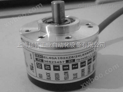
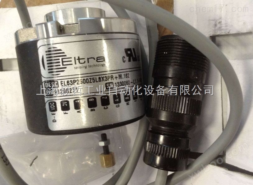
The P+F encoder is a device used to measure rotational speed. The photoelectric rotary encoder can convert mechanical quantities such as angular displacement and angular velocity of the output shaft into corresponding electrical pulses for digital output (REP) through photoelectric conversion. It is divided into two types: single output and dual output. The technical parameters mainly include the number of pulses per revolution (ranging from tens to thousands), and the supply voltage. Single output refers to the output of a rotary encoder being a set of pulses, while a dual output rotary encoder outputs two sets of pulses with a phase difference of 90 degrees between A/B. Through these two sets of pulses, not only can the speed be measured, but also the direction of rotation can be determined.
P+F rotary encoder, German P+F rotary encoder
The signal output includes sine wave (current or voltage), square wave (TTL, HTL), open collector (PNP, NPN), and various forms of push-pull, among which TTL is a long line differential drive (symmetrical A, A -); B,B-; Z. Z -), HTL also known as push-pull or push-pull output, the signal receiving device interface of the encoder should correspond to the encoder.
Signal connection - The pulse signal of the encoder is generally connected to a counter PLC、 Computers, PLCs, and modules connected to computers can be divided into low-speed modules and high-speed modules, with switch frequencies ranging from low to high.
As a single-phase connection, it is used for one-way counting and speed measurement.
A. B two-phase connection, used for counting forward and reverse directions, determining forward and reverse directions, and measuring speed.
A. B, Z three-phase connection, used for position measurement with reference position correction.
A. A -, B -, Z - connections, due to the connection with symmetrical negative signals, the current contributes zero electromagnetic field to the cable, with minimal attenuation, anti-interference *, and can transmit over long distances.
For TTL encoders with symmetrical negative signal output, the signal transmission distance can reach 150 meters.
The P+F rotary encoder is composed of precision components, so when subjected to large impacts, it may damage its internal functions, and full attention should be paid when using it.
Similar Product Recommend