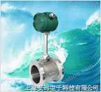
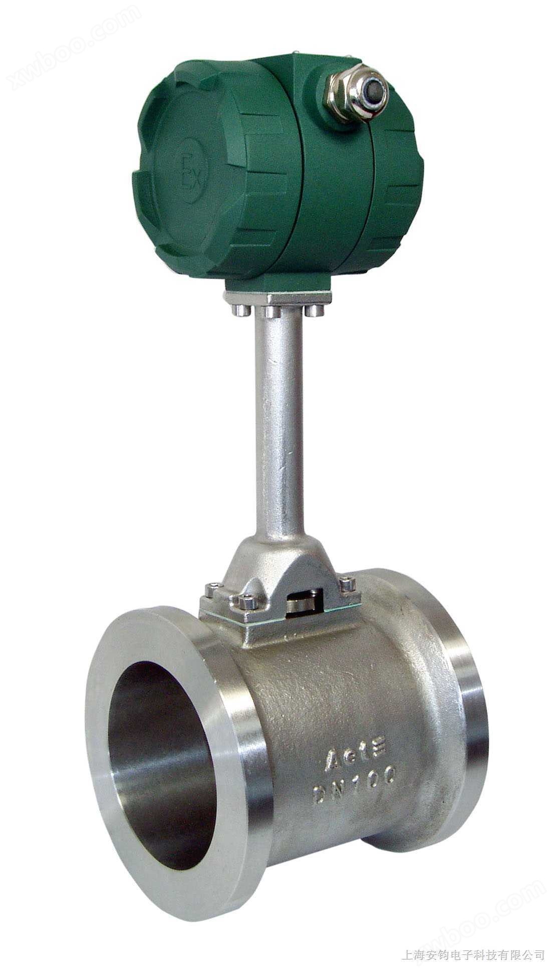
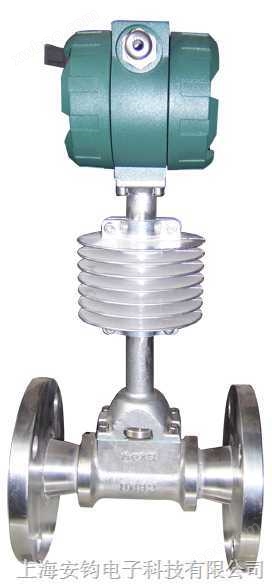
| Plug in vortex flowmeter:
Plug in vortex flowmeterStructural composition and installation
working principle
Insert the vortex street detection head into a specific position of the pipeline and measure the local flow rate at the measurement point. Based on the velocity distribution relationship of the pipeline cross-section, calculate the average velocity value inside the pipeline.
It generally consists of sensors, insertion rod components, ball valves (matched according to requirements), installation short pipes (Φ 100), etc.
Installation steps:
1. Cut a hole slightly smaller than Φ 100 directly above the pipeline where the flowmeter needs to be installed (this requirement applies to horizontal pipelines) and remove any burrs;
2. Place the short pipe with a flange on top of the hole, keep it perpendicular to the pipeline, and weld it firmly;
3. Place the gasket, insert the flowmeter, and connect the flange. If there is a ball valve at this time, first place the ball valve on the short pipe and connect it, then open the ball valve and insert the flowmeter;
Ensure that there is a straight pipe section greater than 15D in front of the flowmeter and 5D behind it.
Technical parameter requirements for vortex flowmeter:
Measurement media: saturated steam, superheated steam, liquid, gas
Accuracy level: Accuracy of 0.5 to 2% depends on Reynolds number, generally ± 1.0% (R) for liquids; Gas, steam
±1.5%(R)±0.3%(R)
Work pressure: ≤ 1.6Mpa or ≤ 2.5Mpa or ≤ 6.4Mpa
Fluid temperature: (-40 ℃, 150 ℃), (-40 ℃, 250 ℃), (-40 ℃, 350 ℃)
Output signal: Three wire pulse or two-wire 4-20mA standard current
Working power supply: DC12V or DC24V
Working environment: Temperature: (-40 ℃, 50 ℃); Humidity:<95% 10-30 ℃
|