-
E-mail
chen@csxcyb.com
-
Phone
13962489399
-
Address
Meili Town, Changshu City, Jiangsu Province
Product Categories
Changshu Xinchang Instrument Sales Co., Ltd

WRR assembled T-shaped thermocouple
NegotiableUpdate on 02/13
- Model
- Nature of the Manufacturer
- Producers
- Product Category
- Place of Origin
Overview
WRR assembled T-shaped thermocouple WR series industrial thermocouple is used as a temperature measurement sensor, usually used in conjunction with temperature transmitters, regulators, and display instruments to form a process control system. It is used to directly measure or control the temperature of fluids, vapors, gas media, and solid surfaces within the range of 0-1800 ℃ in various processes.
Product Details
WRR assembled T-shaped thermocouple
1. Overview of Xinchang WR Series Thermocouples
WR series industrial thermocouples are commonly used as temperature measurement sensors in conjunction with temperature transmitters, regulators, and display instruments to form process control systems. They are used to directly measure or control the temperature of fluids, steam, gas media, and solid surfaces within the range of 0-1800 ℃ in various processes.
A thermocouple is a circuit composed of two conductors with different compositions connected at both ends. When the temperature of the two junction points is different, a thermal current will be generated in the circuit. If there is a temperature difference between the working end and the reference end of the thermocouple, the display instrument will indicate the temperature value corresponding to the thermoelectric potential generated by the thermocouple.
The thermoelectric heating of a thermocouple will increase with the temperature rise at the measuring end, and its size is only related to the thermocouple material and the temperature at both ends, regardless of the length and diameter of the thermoelectric electrode.
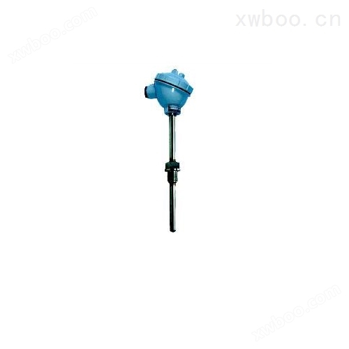
The appearance of various thermocouples often varies greatly depending on their needs, but their basic structures are roughly the same, usually consisting of main parts such as hot electrodes, insulation sleeves, protective tubes, and junction boxes.
2. Main technical characteristics
Measurement range and basic error limit
| Thermocouple category | code name | graduation mark | measurement range | Basic error limit |
| nickel-chromium-Kangtong | WRK | E | 0-800℃ | ±0.75%t |
| nickel-chromium-Nickel silicon | WRN | K | 0-1300℃ | ±0.75%t |
| platinum-rhodium40-platinum | WRP | S | 0-1600℃ | ±0.25%t |
| platinum-rhodium30-platinum-rhodium6 | WRR | B | 0-1800℃ | ±0.25%t |
Note: t is the measured temperature value of the temperature sensing element (℃)
3. Thermocouple time constant
| Thermal inertia level | Time constant (seconds) | Thermal inertia level | Time constant (seconds) |
| Ⅰ | 90~180 | Ⅲ | 10~30 |
| Ⅱ | 30~90 | Ⅳ | <10 |
• Thermocouple nominal pressure: generally refers to the static external pressure that the protective tube can withstand at operating temperature and rupture.
The minimum insertion depth for thermocouples should not be less than 8-10 times the outer diameter of their protective sleeve (except for special products)
• Insulation resistance: When the ambient air temperature is 15-35 ℃ and the relative humidity is less than 80%, the insulation resistance is ≥ 5 megohms (voltage 100V)
Thermocouples with splash proof junction boxes have an insulation resistance of ≥ 0.5 megohms (voltage 100V) when the relative temperature is 93 ± 3 ℃
• Insulation resistance at temperature: The insulation resistance (per meter) between the hot electrode (including double branch) and the protective tube, as well as between the double branch hot electrode and the thermocouple at temperature, should be greater than the values specified in the table below.
| Designated long-term use temperature (℃) | Test temperature (℃) | Insulation resistance value (℃) |
| ≥600 | 600 | 72000 |
| ≥800 | 800 | 25000 |
| ≥1000 | 1000 | 5000 |
4. Model naming method

5. Installation and use of thermocouples
The installation location of thermocouples should be convenient for construction and maintenance. It should be avoided to be located near the furnace door, or too close to the heating element or in areas with strong magnetic fields. The temperature at the junction box should not exceed 100 ℃. The installation position should be kept as vertical as possible, but it must be installed diagonally when there is flow velocity. The outlet of the junction box should face downwards.
Thermocouples with ceramic protective tubes must avoid rapid cooling and heating to prevent bursting, and should be installed in a location that does not obstruct the movement of the heated object. Ceramic protective tubes cannot measure liquid temperature.
Thermocouples should be wired according to regulations, and the leads should avoid heat sources. When wiring, the polarity of the compensating wire should not be reversed. Regularly check the condition of the protective tube and take immediate measures if oxidation or deformation is found. Regular verification is required.
PS: Ordering Notice
When placing an order, please note: (1) Product Name (2) Product Model (3) Index Number (4) Material and Diameter of Protective Tube (5) Length L and Insertion Depth 1 (6) Quantity (7) Fixed Thread M (8) Special Technical Requirements
Similar Product Recommend