-
E-mail
sute@56412027.com
-
Phone
13818304481,13818304482
-
Address
No. 357, Lane 1080, Fuchang Road, Baoshan District, Shanghai
Product Categories
Shanghai Xuji Electric Co., Ltd

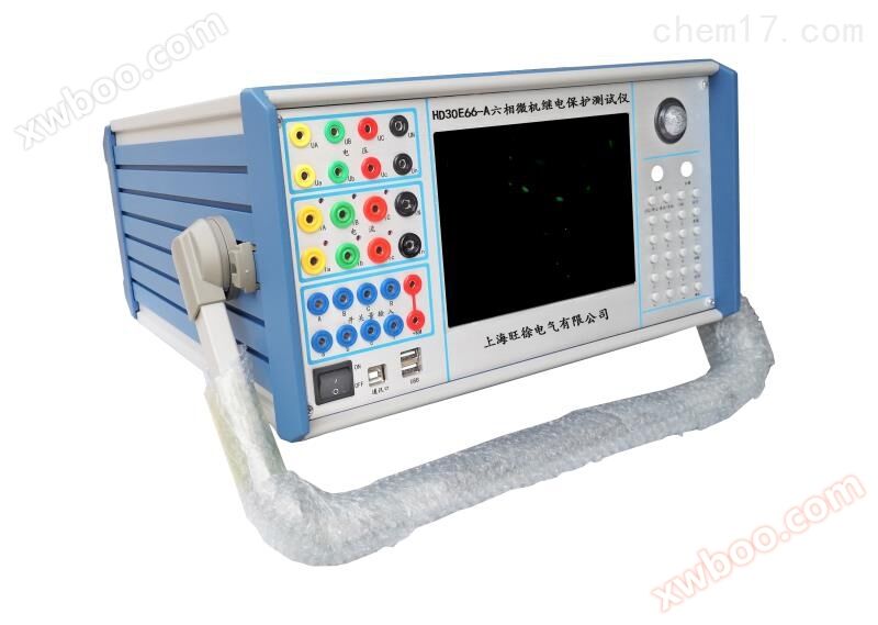
KJ880 Microcomputer Relay Protection Tester
NegotiableUpdate on 07/24
- Model
- Nature of the Manufacturer
- Producers
- Product Category
- Place of Origin
Overview
The KJ880 microcomputer relay protection tester is equipped with an independent dedicated DC auxiliary voltage source output, with output voltages of 110V (1A) and 220V (0.6A), respectively. To be used for relays or protective devices that require DC working power supply.
Product Details
KJ880 Microcomputer Relay Protection Tester
Main features:
1. Meet all on-site testing requirements.
It has a standard six phase current and six phase voltage output simultaneously, with a current of 30A/phase and a voltage of 125V/phase. Six phase current parallel connection can reach 180A. It can be used to test various traditional relays and protection devices, as well as various modern microcomputer protections, especially for transformer differential protection and backup automatic switching devices, making testing more convenient and efficient.
2. All technical indicators fully meet the standards of DL/T624-1997 "Technical Conditions for Microcomputer based Test Devices for Relay Protection" issued by the Ministry of Electric Power.
3. Single machine independent operation, built-in high-performance industrial computer, with a main frequency of 300-600MHz, 128MB of memory, 6-12GB of hard disk, running Windows XP operating system.
4. The domestic industry first adopted imported brushed stainless steel panels, stainless steel keyboards, and touch sensitive mice to overcome the disadvantages of inflexible and easily damaged operation of trackball mice. They also chose an 8.4-inch TFT true color display screen with a resolution of 800 × 600, making single machine operation convenient and durable.
5. The main control board adopts a DSP+FPGA structure and a 16 bit DAC output, which can generate a high-density sine wave of 2000 points per week for the base wave, greatly improving the quality of the waveform and enhancing the accuracy of the tester.
6. The power amplifier adopts high fidelity linear power amplifier, which ensures the accuracy of small current and the stability of large current.
7. It uses a USB interface to communicate directly with the PC without any adapter cables, making it convenient to use.
8. Can be connected to a laptop to run. Laptops and industrial computers use the same software, so there is no need to relearn the operating methods.
9. Equipped with GPS synchronization test function. The device can be equipped with a built-in GPS synchronization card (optional) and connected to a PC through an RS232 port, enabling two testers to perform synchronous testing in different locations.
10. Equipped with an independent dedicated DC auxiliary voltage source output, with output voltages of 110V (1A) and 220V (0.6A) respectively. To be used for relays or protective devices that require DC working power supply.
11. It has software self calibration function, which avoids the need to open the chassis and adjust the potentiometer to calibrate accuracy, greatly improving the stability of accuracy.
KJ880 Microcomputer Relay Protection Tester
Hardware composition:
1. Built in high-performance industrial control computer
This device uses a high-performance industrial computer as the control computer, equipped with 128M memory, 6-12G hard drive, pre installed Windows XP operating system, panel with 8.4 "800 × 600 resolution TFT true color LCD display, stainless steel optimized keyboard and touch mouse, which can be used directly without external keyboard and mouse. The device panel is equipped with two USB interfaces for convenient data access, data communication, and software upgrades.
2. DSP digital signal processing system
The 6000 series DSP controller is used as the core, and FPGA programmable logic devices output waveforms. Due to the use of DDS hardware output waveform technology, the waveform frequency and phase accuracy are quite high. At the same time, the system communicates directly with the industrial computer using USB2.0 interface, making data communication stable and reliable.
3. D/A and A/D conversion
By using a high-precision D/A converter and an active low-pass filter, the output waveform is smoothed and the amplitude frequency characteristics are excellent. At the same time, the control system also retains 12 channels of 12 bit A/D conversion circuits, which can real-time collect the output waveforms of 12 analog signals and display the actual output waveforms, amplitudes, and phases on the screen through software.
4. The high-precision linear voltage and current power amplifier system of the microcomputer relay protection tester adopts a high-performance linear amplifier direct coupling output method for current and voltage, allowing the current and voltage sources to directly output AC and DC waveforms, and can calculate and output various combined waveforms such as square waves, various harmonics superposition, and fault transient waveforms through software. It can simulate the current and voltage characteristics of various short-circuit faults well. The power amplifier circuit adopts imported high-power high fidelity modular power devices as the power output stage, combined with carefully designed heat dissipation structure, with sufficient power redundancy and thermal capacity. The power amplifier circuit has complete overheating, overcurrent, overvoltage and short-circuit protection, and the current circuit allows open circuit without damaging the device. The panel has a current open circuit indicator light to facilitate users in checking whether the wiring is correct. At the same time, the panel also has a voltage overload or short circuit indicator light. When a short circuit occurs in the voltage circuit (with output), the indicator light will light up and activate the buzzer alarm. The high current time limit adopts unique hardware and time limit circuit, overcoming the shortcomings of traditional software time limit, making high current use safer and more reliable.
Similar Product Recommend