-
E-mail
2559293216@qq.com
-
Phone
15216878095
-
Address
13A11, 14th Floor, Hongyuan Hotel Business Building, No.1 Hongyuan Road, Nancheng District, Dongguan City, Guangdong Province
Product Categories
Shanghai Yingzhe Industrial Automation Equipment Co., Ltd. Dongguan Branch
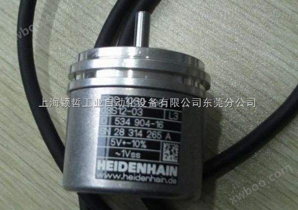
HEIDENHAIN encoder from Germany is currently on sale at a discount
NegotiableUpdate on 03/09
- Model
- Nature of the Manufacturer
- Producers
- Product Category
- Place of Origin
Overview
HEIDENHAIN encoder from Heidenhain, Germany * discounted sales: encoders can be divided into contact and non-contact types according to the reading method; According to the working principle, encoders can be divided into two categories: incremental and linear. An incremental encoder converts displacement into a periodic electrical signal, which is then converted into count pulses to represent the magnitude of displacement in terms of the number of pulses. Each position of the encoder corresponds to a specific digital code, so its indication is only related to the starting and ending positions of the measurement, and not to the intermediate process of the measurement.
Product Details
HEIDENHAIN encoder from Germany is currently on sale at a discount:
Heidenhain has branches and companies in 49 locations, which can be considered high-quality standards. Heidenhain records length and angle through certification, ISO 9001 quality system models, and as a German calibration service (dkd) checkpoint. As long as the product's service life and recyclable design adhere to the environmental declaration of careful use of resources and optimization of energy consumption on other prerequisites, while complying with the ISO 14001 series standards.
Heidenhain develops and produces grating rulers, angle encoders, rotary encoders, digital display devices, and numerical control systems. Heidenhain's products are widely used in machine tools, automation machines, especially in the semiconductor and electronic manufacturing industries.
Heidenhain's products are the guarantee for efficient and effective operation of machine tools and large equipment. Since its reconstruction in Traunreut, Germany in 1948, Heidenhain has delivered over 5 million sets of linear grating rulers, 11 million sets of rotary encoders and angle encoders, 460000 digital display devices, and nearly 235000 sets of TNC CNC systems.
In order to further cater to the expanding needs of customers in China, Heidelberg Germany headquarters has established a new factory area covering an area of 14650 square meters in the Tianzhu Airport Industrial Zone in Beijing with a total investment of 30 million US dollars, taking a step towards application research and development and production manufacturing in China. Heidenhain China has fully transplanted the production technology, management experience, and quality standards of its German headquarters, ensuring the implementation of Heidenhain Germany's quality requirements and service philosophy in China.
All Chinese employees of Heidenhain will uphold Heidenhain's mission: to provide customers with excellent services, high-quality products, and continuously improve themselves. We firmly believe that we can become the closest partner for our customers in developing their respective careers
HEIDENHAIN encoder from Germany is currently on sale at a discount:
HEIDENHAIN - Quality and Environmental Protection
edit
HEIDENHAIN company has obtained ISO9001 quality system certification for its high-quality standards and has been designated as a German length and angle unit calibration service inspection station. But HEIDENHAIN company has more than just technology: HEIDENHAIN company also sets standards for the environmental protection field. On the one hand, it is necessary to have a long product service life and a recyclable design, and on the other hand, it is necessary to have meticulous resource utilization and efficient energy consumption, which are prerequisites for complying with the ISO14001 environmental declaration.
Dr. Johannes Heidenhain's company develops and produces high-quality linear grating rulers, angle encoders, rotary encoders, digital display devices, and numerical control systems. Heidenhain's products are mainly used in the production and processing equipment of precision machine tools and electronic components.
Installation and Usage
Mechanical installation and use of rotary encoders:
The mechanical installation of the rotary encoder includes high-speed end installation and low-speed end installation
Various forms such as installation of auxiliary mechanical devices.
High speed end installation: Installed on the shaft end of the power motor (or gear connection), this method has the advantage of high resolution. Due to the 4096 turns of the multi turn encoder, the number of motor rotations within this range can be fully utilized to improve resolution. The disadvantage is that there is gear clearance error in the back and forth travel of moving objects after passing through the deceleration gear. It is generally used for one-way high-precision control positioning, such as roll gap control in steel rolling. In addition, the encoder is directly installed at the high-speed end, and the motor vibration must be small, otherwise it is easy to damage the encoder.
Low speed end installation: Installed after the reduction gear, such as the shaft end of the winch wire rope drum or the shaft end of the last reduction gear. This method has no gear backlash, and the measurement is more direct and accurate. This method generally measures long-distance positioning, such as various lifting equipment, feeding trolley positioning, etc.
Installation of auxiliary machinery:
Commonly used ones include gears and racks, chain belts, friction wheels, rope winding machinery, etc.
working principle
A photoelectric encoder with a central axis, on which there are circular markings for light and dark,
There are photoelectric emitting and receiving devices to read and obtain four sets of sine wave signals combined into A, B, C, and D. Each sine wave has a phase difference of 90 degrees (360 degrees relative to one cycle). By reversing the C and D signals and superimposing them on the A and B phases, stable signals can be enhanced; Additionally, output a Z-phase pulse for each revolution to represent the zero reference position.
Due to the 90 degree difference between phase A and phase B, the forward and reverse rotation of the encoder can be determined by comparing whether phase A is ahead or phase B. By using the zero position pulse, the zero position reference position of the encoder can be obtained. The materials of encoder encoders include glass, metal, and plastic. Glass encoders deposit very thin engraved lines on glass, which has good thermal stability and high accuracy. Metal encoders directly engrave lines with or without lines, which are not fragile. However, due to the thickness of metal, the accuracy is limited, and its thermal stability is one order of magnitude worse than that of glass. Plastic encoders are economical and have low cost, but their accuracy, thermal stability, and lifespan are all inferior.
:
Resolution - The number of lines provided by an encoder for each 360 degree rotation is called resolution, also known as resolution division or directly referred to as number of lines. Generally, it ranges from 5 to 10000 lines per rotation.
Common Faults
1. Encoder malfunction: refers to the failure of the encoder's own components,
Resulting in its inability to generate and output correct waveforms. In this case, it is necessary to replace the encoder or repair its internal components.
2. Encoder connection cable fault: This type of fault has the highest probability of occurrence and is often encountered during maintenance, and should be a priority factor to consider. Usually, it is due to open circuit, short circuit or poor contact of the encoder cable, in which case the cable or connector needs to be replaced. Special attention should also be paid to whether the loosening caused by loose cable fixation leads to welding or circuit breaking. In this case, the cable should be clamped tightly.
3. Encoder+5V power supply drop: refers to the situation where the+5V power supply is too low, usually not lower than 4.75V. The reason for the low voltage is due to power supply failure or high resistance of the power transmission cable, which causes losses. In this case, the power supply needs to be repaired or the cable needs to be replaced.
4. The voltage drop of the encoder battery: This fault usually has a clear and meaningful alarm,
At this point, the battery needs to be replaced. If the reference point position memory is lost, the operation of returning to the reference point must also be performed.
5. The shielded wire of the encoder cable is not connected or detached: this will introduce interference signals, make the waveform unstable, and affect the accuracy of communication. It is necessary to ensure reliable welding and grounding of the shielded wire.
6. Loose installation of encoder: This fault can affect the accuracy of position control, causing excessive positional deviation during stopping and movement, and even generating servo system overload alarm as soon as the machine is turned on. Please pay special attention.
7. Grating contamination can cause a decrease in signal output amplitude, and it is necessary to gently wipe off the oil stains with degreasing cotton.
Wiring method
A rotary encoder is a photoelectric rotary measuring device that directly converts the measured angular displacement into a digital signal (high-speed pulse signal).
If encoders are classified based on signal principles, there are incremental encoders and type encoders.
We usually use incremental encoders, which can directly input the output pulse signal of the rotary encoder to the PLC, and use the PLC's high-speed counter to count its pulse signal to obtain measurement results. Different models of rotary encoders have different numbers of output pulses. Some rotary encoders output three-phase pulses of A, B, and Z, some only have two phases of A and B, and the simplest one only has phase A.
:
The encoder has 5 leads, including 3 pulse output lines, 1 COM terminal line, and 1 power line (OC gate output type). The power supply of the encoder can be an external power supply or directly use the DC24V power supply of the PLC. The "-" end of the power supply should be connected to the COM end of the encoder, and the "+" end should be connected to the power supply end of the encoder. The COM end of the encoder is connected to the input COM end of the PLC, and the A, B, and Z phase pulse output lines are directly connected to the input end of the PLC. A and B are pulses that are 90 degrees apart, and the Z phase signal has only one pulse when the encoder rotates once, usually used as a basis for zero point. When connecting, attention should be paid to the response time of the PLC input. The rotary encoder also has a shielded wire, which should be grounded during use to improve anti-interference performance.
Encoder ----------- PLC
A-----------------X0
B-----------------X1
Z------------------X2
+24V------------+24V
COM------------- -24V-----------COM
Similar Product Recommend