-
E-mail
818155158@163.com
-
Phone
13798207140
-
Address
Building C, No.1 Hengling Middle Road, Nianfeng Village, Pingdi Street, Longgang District, Shenzhen
Product Categories
Shenzhen Chuanbenst Refrigeration Equipment Co., Ltd


Combination purification air conditioner
NegotiableUpdate on 04/20
- Model
- Nature of the Manufacturer
- Producers
- Product Category
- Place of Origin
Overview
The air volume of the combined purification air conditioner ranges from 3500m3/h to 200000m3/h, with 30 specifications and a total of 12 functional sections for users to freely choose from. Mainly suitable for air purification systems in various clean rooms. Such as industrial electronics factories, precision machinery manufacturing factories, textile workshops, automotive spray painting workshops, GMP pharmaceutical factories, cosmetics, food factories, pure water workshops, hospital operating departments, ICUs and other occasions.
Product Details
- Combination purification air conditionerCharacteristics and Structure
Precision air conditioning, also known as constant temperature and humidity air conditioning, has functions such as cooling, dehumidification, heating, humidification, etc. It can provide an artificial climate to keep indoor temperature and relative humidity constant within a certain range. A typical precision air conditioner can keep the ambient temperature between 20-25 ℃, with a maximum deviation of ± 1 ℃; The relative humidity is between 50% and 60%, with a maximum deviation of 10%. It is a relatively complete air conditioning equipment, and its temperature and humidity control range is determined according to the on-site usage requirements.
The refrigeration circuit includes a compressor and an external balanced thermal expansion valve used to maintain a certain degree of superheat of the refrigerant flowing to the evaporator. The outdoor condenser is air-cooled. Dry nitrogen gas is filled in each refrigeration circuit at the factory. The owner is responsible for connecting the unit to the outdoor condenser and filling it with refrigerant.
Airflow selection: refers to the way air circulation is carried out during the operation of air conditioning, generally including three air supply methods: independent upward air supply, independent downward air supply, and simultaneous upward and downward air supply. The upper air supply adopts a pipeline to supply air from the ceiling of the computer room from top to bottom, which is suitable for quickly reducing the temperature and humidification of the computer room; Downward air supply is from the floor and corners of the computer room, suitable for quickly raising the temperature and dehumidification of the computer room.
- construction technology
2.1 Preparation work
2.1.1 Operating limit: The unit is designed to operate within the operating range (clearly indicated for each unit). Exceeding this limit will cause the compressor to jam, and resetting to normal can only be done manually. The condenser is installed below the indoor unit. If the condenser is installed 6 meters above the unit, an oil trap should be installed every 6 meters.
2.1.2 Positioning
Air conditioning units are divided into indoor units and outdoor units. The positioning of outdoor units mainly considers gap space and maintenance distance. The installation of indoor units mainly considers the position of air inlet and outlet and their impact on airflow organization; First, determine the position of the precision air conditioning unit and floor air vents based on the size and shape of the room and the location of the equipment units in the computer room.
2.1.3 Installation
1. The production and fixation of the bracket: Firstly, check and confirm that the ground is flat, and the structural form and external dimensions of the vibration isolation steel support and hanger should comply with your design or equipment technical documents. The welding should be firm, and the weld seam should be full and uniform.
2. Production and installation of wind caps: Determine the size and form of the wind caps based on the unit bracket and the position of the unit's air outlet, and ensure that the production structure is reliable.
3. Unit positioning: After fixing the bracket and making and installing the air cap for insulation, the unit is positioned.
4. Refrigerant pipeline connection:
The air conditioning unit needs to be pressurized with helium gas to 3 bar. The indoor unit needs to be purged with helium gas (3bar), and after connecting the system and evacuating it, immediately weld the base and connecting parts. Then install the copper pipe.
1) The installation of copper pipes should be as short as possible to reduce refrigerant charge and pressure difference. When arranging horizontal air pipes, there should be a 1% downward slope in the direction of refrigerant flow.
2) Reduce the number of bends and increase the diameter of the bends.
3) If pipelines are close to electrical wires, they should be insulated to prevent damage to the insulation of the wires.
4) There should be a gap of more than 20mm between the trachea and the liquid tube, and if not, they should all be insulated.
5) Both horizontal and vertical pipes should have shock-absorbing brackets (including rubber pads) installed every 1.5-2 meters.
6) When laying pipelines, pay attention to the following:
Welding: All welding must be copper welding; Avoid butt welding, use a reamer to expand the pipe or weld the sleeve; Use silver solder and the correct tools; Ensure good welding, as refrigerant leakage and poor welding can cause serious damage to equipment in the future due to refrigerant leakage; Use large-diameter elbows (with a diameter not less than the pipe diameter), and preheat elbows for hard copper bends. Do not overheat during pipeline welding to minimize the degree of oxidation.
7) Connect the pipeline to the condenser.
The condenser is equipped with butt welded pipe interfaces: cutting pipes, expanding ports, and welding to the interfaces.
The condenser has a threaded interface: install a flange for connection. Pay attention to the flow direction of the refrigerant (see the markings when connecting the refrigerant).
8) Thermal insulation
Insulation work can only be carried out on a clean and dry surface without any pollutants. The insulation of pipelines passing through sleeves and holes must be continuous. The insulation joints must be arranged in a staggered manner and tightly sealed with 50mm wide aluminum moisture-proof patches. Use approved adhesive to evenly and firmly attach the insulation material to the surface of the pipeline.
8) Blow the pipeline in the following way:
a) Block the unsealed joints of the pipeline;
b) Connect to helium cylinder, install pressure reducing valve (maximum 10 bar), and connect to 1/4 "condenser valve;
c) Inject helium gas into the pipeline;
d) Immediately remove the pipe head;
e) Repeat a) to d) several times.
9) Open all closed valves of the indoor unit.
10) The indoor unit is purged with helium gas (3bar), and the filling valve is opened so that all branches in the circuit (such as the storage tank, low-pressure side, and compressor discharge) have been flushed.
11) Weld the base and connecting parts of the indoor unit.
12) Weld the pipeline to the interface of the air conditioner.
13) Connect the refrigerant safety valve to the outside using O16 copper pipe.
5. Installation of water pipes
1) The water supply pipe adopts plastic lined steel pipe with a diameter of DN15; The drainage pipe (condensate pipe, sewage pipe) adopts PPR hot water pipe with a diameter of Φ 50. The holes for water supply and drainage pipes entering the unit shall be sealed with silicone, and a 5cm high water stop shall be installed around the unit and floor drain.
The connection of the water pipe has a 2% slope towards the discharge outlet; A water trap must be installed 30mm below the drainage pan; The condensate pipe and sewage pipe merge after leaving the unit; Connect a bypass pipe between the water supply pipe and the drainage pipe, and install a valve control to flush the drainage pipe during operation and maintenance; Use a tee instead of an elbow at the grounding leak of the drainage pipe to prevent air blockage.
6. Vacuum pumping and refrigerant charging
1) Vacuum pumping and refrigerant charging: Verify the refrigerant model to be used and the data on the air conditioner and compressor panels.
2) Preparation before R22 charging:
Open all valves of the system, including those that have been purged (indoor unit and condenser), and through this operation, all components of the system can be evacuated. Connect a suitable and efficient vacuum pump. Connect the system to the refrigerant tank. Vacuum the system to a pressure of 0.7 mbar and maintain it for 30 minutes. The pressure of the system must be measured by a vacuum pressure gauge. If vacuuming fails, it indicates a leak.
3) Complete the vacuuming process as follows:
 a) Close the valve on the vacuum pump;
b) Keep the refrigerant tank vertical, open the valve, and allow gaseous refrigerant to be injected into the system;
c) When the pressure of the gaseous refrigerant, condenser, and storage tank in the pipeline is balanced with the refrigerant tank, the charging preparation is completed;
d) At this point, the vacuum pump and refrigerant tank can be dismantled according to the following method: close the valve of the refrigerant tank; Close the 1/4 three-way plug valve and all connecting valves in the pipeline. Fill the unit with refrigerant until the bubbles in the sight glass are eliminated and the working conditions of the entire refrigerant cycle are normal;
4) Check all joints with a leak detector. If a leak is found, the pipeline and condenser should be emptied. After welding the leak point, repeat the steps.
3、 Unit start-up and commissioning
3.1 Preparation before starting: Before starting the precision air conditioning unit, confirm that the electrical connections are accurate and correct; Manually start the compressor to ensure that the unit is not in a dehumidification state; Ensure a overheating degree of 7-8 ℃.
3.2 * To avoid damage to the compressor, ensure that the crankcase is preheated for no less than 4 hours before turning on the air conditioner.
3.3 Start the air conditioner according to the following steps:
1. Open all valves identified in the manual on the refrigerant circuit;
2. Open all valves identified in the manual on the water system circuit;
3. Ensure that refrigerant charging is completed.
4. Check with a leak detector to ensure that there is no refrigerant leakage in the system. If there is a leak, it needs to be repaired and filled with refrigerant.
5. In the "micro panel" control system, the "individual standard" is set as the standard setting at the factory. The "individual standard" can easily turn on the unit, and the main switch indicator on the electrical panel is in the rotating state. After the unit is turned on, the yellow LED on the microvan board lights up due to power on.
If the LED does not light up: check the power supply of the electrical panel; Check protective devices (such as thermal protection switches); Check the fuse.
6. Turn off the QF1 switch.
7. Confirm that the crankcase heater is heating up.
8. Check that the water system is not leaking.
9. For D-type and H-type units: Use the vent valve on the chilled water coil to release the air in the chilled water circulation.
10. Install outdoor condensers and free coolers, and power them on before starting.
11. Turn off all MCB switches on the electrical panel.
12. Check all phase to phase voltages of the power supply.
13. Check all phase to phase voltages of the outdoor condenser and free cooling power supply installed.
14. Confirm that the compressor has been preheated for no less than 4 hours before the unit is started.
15. Press the ON-OFF switch to start the unit.
16. Check the electrical performance of all components.
17. Check the electrical performance of the installed outdoor condenser/free cooler.
18. If the compressor produces loud noise or abnormal noise. It is necessary to reverse the power phase supplied to the scroll compressor, as the compressor can only rotate in one direction.
19. Confirm that the direction of the fan is correct (see the arrow on the fan).
20. Ensure that all control system settings are correct and there are no alarms.
21. Confirm the direction of water flow.
22. When starting the compressor of a closed cycle unit, ensure that the water pump is also started.
23. Confirm that the air inlet can operate normally.
Once the unit is operating under load, check the operation of the components as follows:
·Confirm whether the fan is running normally;
·Confirm that the temperature and relative humidity have been controlled, and that the humidification tank and heater have been activated as needed;
·Confirm that the compressor is running as required;
·Confirm that the chilled water valve has been opened as required;
·Confirm that the fan controller installed with outdoor condenser/free cooler has been properly debugged and controls the fan to operate normally.
3.4 Startup and Shutdown
Always ensure that each crankcase is preheated. Short term shutdowns should also maintain power supply to the crankcase. Turn on the ON/OFF switch located on the left side of the unit for operation. If the remote control switch for ON/OFF is not installed, the green LED light on the micro panel will light up, and at the same time, the LED under the ON/OFF switch will also light up. The fan immediately starts (running continuously after the unit is turned on), and after 2 minutes of adjustment, the cooling (compressor), heating (electric heater), humidification, and dehumidification functions are activated. Press the OFF button on the ON/OFF switch to stop the machine.
3.5 Automatic restart
If required, the unit can automatically restart after power is restored after a power outage. If there is a power outage for several hours, in order to prevent automatic cold start of the compressor, the unit should be shut down before power supply, and the compressor should be preheated before starting the unit after power supply.
3.6 Perform load operation for 48 hours and check if it meets the design requirements.
2.3.2 Mechanical and Electrical Installation Engineering
1. Reliability assurance of electromechanical equipment
(1) Ensure the reliability of equipment procurement results
The procurement of equipment and materials will adopt a multi-dimensional selection approach, with product quality and reliability as the criteria for material selection and positioning. Specially configure necessary testing equipment and, if necessary, commissionapprovedLaboratories with corresponding qualifications are conducting this work. Materials and equipment entering the site must be inspected for material certificates and qualification certificates, and sealed. They must be strictly inspected in accordance with specifications, drawings, and construction requirements in conjunction with Party A, the supervisor, and others. Any non-conforming materials must be immediately returned and must not be used for any construction project.
(2) Reliability of Line Construction
Strengthen quality control during the construction process, conduct strength and tightness tests on water pipelines to ensure that there will be no water leakage. Before threading the electrical conduit, clean it completely to ensure that the inner wall of the conduit is smooth and will not damage the insulation layer of the wire. All kinds of equipment are securely lifted and reinforced with reliable measures, reducing risks to zero.
(3) Comprehensive and comprehensive debugging
① After the installation of various mechanical and electrical systems, a comprehensive system debugging is carried out to ensure the normal operation of the system for 72 hours. Adjustments and tests are made according to the design parameters to ensure that the performance meets the design requirements.
② After the mechanical and electrical systems reach the designed operating conditions, all mechanical and electrical systems will be operated for comprehensive mechanical and electrical debugging, and the linkage of each system will be debugged. Ensure accurate control and linkage of each system.
③ After the system is fully put into use, a dedicated person is responsible for tracking and maintaining the operation status of the electromechanical system, timely adjusting any problems that may arise during system operation, and gradually bringing the electromechanical system to its optimal state.
(4) Necessary spare parts
While ensuring the reliability of the electromechanical system, it is necessary to consider the possibility of unexpected factors and provide sufficient spare parts for consumables to ensure that maintenance problems can be solved in the shortest possible time in emergency situations.
2. Key points of supervision management and coordination between mechanical and electrical engineering and general contracting
(1) Management principles of general contractor for mechanical and electrical engineering construction
The general contractor's principles for mechanical and electrical construction and management: The project general contracting department, on behalf of the enterprise legal person, should strictly fulfill the contractual agreements with or the tenderer, be responsible to the tenderer, understand and meet the intentions and requirements of the tenderer and the design party; Implement goal management and full process control for all subcontractors involved in this project to ensure the achievement of management goals.
Based on the above principles, the electromechanical specialty of this project will adopt the following methodsgeneral contractorAdministration:
① Goal management: It is required to establish overall and phased goals during the general contracting management process, including quality, progress, safety, civilized construction, etc. Under the premise of clear goals, manage, monitor, coordinate, and evaluate each subcontracting unit.
② Institutional management: Based on years of project management experience, it is required to establish a general contracting management system that is in line with the actual situation on site, including the following contents: general contracting cooperation service work agreement; Subcontracting entry and exit management system; Work meeting system; Subcontracting quality management system; Subcontracting progress management system; On site civilized construction and environmental management system; Subcontracting safety management system; Subcontracting Technical Data Management System; General layout management system; Subcontracted finished product protection system; Post warranty service system, etc.
③ Process management: While conducting goal management, the focus is on process tracking management to ensure that the goals of each stage meet the corresponding requirements during the construction process. During the process, track and inspect quality, progress, safety, and civilized construction. If any problems are found, immediately provide feedback and urge rectification. Conduct timely re inspection to ensure that the problems are resolved during the construction process.
④ Coordination management: Clarify the responsibilities of both parties through contracts and agreements with each subcontractor, use the contract and agreement as the basis for construction general contracting management, use the overall construction period network plan of the general contractor as the benchmark, reasonably arrange the construction time of each subcontractor, organize process interweaving, and timely solve technical, progress, and quality problems of each professional subcontractor by the general contracting company; Resolve various conflicts between the main and sub contractors through daily engineering coordination meetings and weekly engineering meetings, in order to ensure the smooth progress of the entire construction project and achieve various goals.
(2) Key coordination points for general and subcontracting supervision in different construction stages
① Coordination and cooperation before subcontracting construction
Before the subcontractor enters the site, they shall provide the "Subcontractor Entry Notice" to the subcontractor. This "Subcontracting Notice" is to strengthen the close cooperation between the general contractor and the general contractor, ensure that the general contractor is easy to coordinate during the construction of the project, and effectively unify the management of each subcontractor. The main contents of the "Subcontracting Notice" include: entry procedures, entry safety management procedures, material and machinery management procedures, quality management procedures, on-site management procedures, technical and data management procedures, etc. At the same time, in order to ensure the smooth construction of the subcontractor, sufficient and barrier free working surfaces shall be provided in a timely manner after the subcontractor enters the site, and temporary facilities such as water, electricity, existing mechanical equipment, scaffolding, office and storage land shall be provided. Mechanical and electrical engineering majors should analyze the characteristics of civil construction, adjust their construction sequence and process methods, achieve * quality with reasonable construction time, and ensure the overall project is of high quality and efficiency.
② Coordination and cooperation during the construction phase of the main structure
The coordination during the structural construction phase mainly involves installation, reservation, and embedding. Civil construction should create conditions for reservation and embedding, and carry out professional signing work; For concealed works, professional signatures must be obtained before construction can proceed. For the embedded parts or reserved holes that need to be pre embedded in civil engineering, the general contracting department shall coordinate them uniformly. Before construction, the civil engineering should check with the professionals, clearly indicate them on the civil engineering drawings, and inspect and verify them on the construction site. The confirmation work should be done through joint signature to prevent missing or incorrect burial, in order to ensure the construction quality of the concrete surface layer. For the parts that are pre embedded by the profession itself, civil engineering should provide the reference lines required for pre embedded construction and remind the profession to insert them into the construction in a timely manner. And reserve construction time for professional pre embedding.
③ Coordination and cooperation during the initial decoration stage
At this stage, the mechanical and electrical major needs to closely cooperate with civil engineering and decoration, clarify their respective construction scope before construction, and make arrangements for process interweaving and work surfaces. Before the initial decoration, determine the decoration method for each room and mark it on the floor plan. According to the different methods of each surface layer, polish or rub the plaster surface to avoid potential hazards to the surface layer construction.
The piping and wiring inside the walls and floors should be completed before the construction of the walls and floors, and professional signatures should be done during the handover. For mechanical and electrical specialties that require slotting on walls and floors, an application should be submitted to the general contracting department in advance. After approval, mechanical cutting must be used to ensure that the trunking is straight and deep.
④ Coordination and cooperation during installation and decoration construction stages
Before entering the installation and decoration construction, the civil engineering department will hand over the elevation and axis of each floor to the installation and decoration team in writing, and each profession will review them together to effectively carry out professional signing work.Combination purification air conditioner
Before the mechanical and electrical installation construction, the positions of various professional pipelines should be comprehensively arranged, and the construction sequence from top (or inside) to bottom (or outside) should be determined. Before concealing pipelines and other items in decoration projects, the installation profession must complete pipeline pressure testing, branch air leakage testing, and electrical insulation testing, and undergo concealed acceptance by the management engineer. Before the construction of the decorative ceiling, the decoration department should coordinate with various professions to determine the positions, reserved dimensions, and reinforcement measures of the lighting fixtures, air vents, alarm probes, and broadcast speakers, and coordinate the process interweaving, work surface arrangement, and finished product protection of each profession.
Combination purification air conditionerEach functional segment
The combined clean air conditioning unit has 30 specifications ranging from 3500m3/h to 200000m3/h, with a total of 12 functional sections for users to freely choose from. Mainly suitable for air purification systems in various clean rooms. Such as industrial electronics factories, precision machinery manufacturing factories, textile workshops, automotive spray painting workshops, GMP pharmaceutical factories, cosmetics, food factories, pure water workshops, hospital operating departments, ICUs and other occasions.
Classified by structural type, it can be divided into horizontal, vertical, and suspended ceiling types; Classified by usage characteristics, it can be divided into general units, fresh air units, purification units, and units (such as rooftop units, subway units, computer room units, etc.); It can also be classified by specifications, and the basic specifications of the unit can be represented by the rated air volume.
The setting of the functional section of the purification unit should be determined according to the production process or clean room requirements, which is a basic principle. The merging and selection of purification unit functional sections should be closely integrated with the design of the air conditioning room.
Microbial contamination points in the purification unit must be controlled. Due to the suitable structure, temperature and humidity for the growth of bacteria and other microorganisms, the box, filter, muffler, humidifier and other components of the purification unit have become potential microbial contamination points that must be controlled. If the unit casing is undamaged, rust free, resistant to disinfection, has good insulation and sealing performance, antibacterial materials widely used in refrigerators can be used; The performance indicators of the filter meet the requirements; Silencers, humidifiers, etc. do not retain condensable substances; Regularly clean or disinfect the unit.
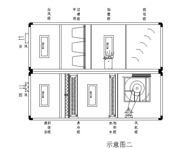
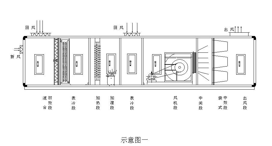
Each functional section of the air conditioning unit: 1. The new return air mixing section. The position of the new return air outlet can be set at the end, top, or left and right sides according to the design requirements. If it is different from this sample, the specific opening position should be provided. A regulating valve can be installed on the new return air outlet, and the actuator has three types: manual, electric, and pneumatic, which can be selected by the user.
2. There are two types of filtration stages: primary and medium efficiency filtration, equipped with diamond shaped bag type and four peak bag type, and can also be equipped with automatic winding type. The filter material is made of high-quality polyester non-woven fabric, and the filter is equipped with a quick installation and removal mechanism, a cover display, and an alarm device.
3. The new exhaust section (also known as the flat top split air mixing section) is equipped with a primary return air valve inside the box. The box top before and after the valve is equipped with an exhaust outlet and a fresh air outlet, and is equipped with a regulating valve. Its function is to supply air conditioning units with partial return air when there is a return air fan, so that the fresh air and primary return air are mixed according to the required ratio; When using a DC system during the transition season, the return air valve should be closed once, and the exhaust and fresh air valves should be fully opened.
4. The energy recovery section is used for cross split air mixing and exhaust energy recovery in a dual fan system. There is a return air valve inside this section of the box, and the top is an energy recovery device. It is a method of indirectly cooling (heating) fresh air by using the cold (hot) exhaust air. The fresh air passes through a plate type energy recovery device and can recover about 60% of the sensible heat energy of the exhaust air. At the same time, the exhaust and fresh air do not come into direct contact, making it particularly suitable for energy recovery in DC air conditioning systems that eliminate harmful gases indoors. When used in a DC system, the return air valve should be closed once. Hazardous gas sites should have separate exhaust systems and should not use this section.
5. The intermediate section (maintenance section) is used for connecting the transition section and providing internal maintenance lighting for the unit. Before the filtering section, a middle section must be set up before and after the surface cooling section, heating section, and silencing section
6. The secondary return air section is connected to the middle section of the secondary return air pipe, and a regulating valve can be installed at the top. It is equipped with manual, electric or pneumatic regulating mechanisms, which can be selected by the user. This section can also be combined with the air supply fan section.
7. The surface cooler in the cold section adopts a structure of four, six, and eight rows of copper tubes with aluminum foil in series. The aluminum foil is in the form of double flanged corrugated edges. The large bent pipe heat exchanger reduces 60% of the welding bends, improves the mechanical expansion form of heat exchange, and ensures the contact performance of the heat exchanger. The heat exchanger is divided into fixed and rotary types, and users can choose one according to their needs. The heat medium is steam or hot water.
Classified by structural type, it can be divided into horizontal, vertical, and suspended ceiling types; Classified by usage characteristics, it can be divided into general units, fresh air units, purification units, and units (such as rooftop units, subway units, computer room units, etc.); It can also be classified by specifications, and the basic specifications of the unit can be represented by the rated air volume.
The setting of the functional section of the purification unit should be determined according to the production process or clean room requirements, which is a basic principle. The merging and selection of purification unit functional sections should be closely integrated with the design of the air conditioning room.
Microbial contamination points in the purification unit must be controlled. Due to the suitable structure, temperature and humidity for the growth of bacteria and other microorganisms, the box, filter, muffler, humidifier and other components of the purification unit have become potential microbial contamination points that must be controlled. If the unit casing is undamaged, rust free, resistant to disinfection, has good insulation and sealing performance, antibacterial materials widely used in refrigerators can be used; The performance indicators of the filter meet the requirements; Silencers, humidifiers, etc. do not retain condensable substances; Regularly clean or disinfect the unit.
Combination air conditioner,air conditioning unit,Selection of modular air conditioning units,Principle of modular air conditioning unit,packaged air conditioner
Sample of modular air conditioning unit,Standard for modular air conditioning units,Unit type air conditioning unit,Combination air handling unit,Variable air volume air conditioning unit,air handling unit,Combination air handling unit,Selection of Air Handling Unit Model,Combination air conditioning unit,Horizontal air handling unit,Ceiling mounted air handling unit,Fresh Air Handling Unit,Air compressor unit,Working principle of air handling unit
Note:1.Unit performance condition: refrigeration:Return air condition, fresh air volume<10%, temperature of air dried bulb27℃, entering rheumatic bulb temperature19.5℃,outlet water temperature7℃,return water temperature12Heating at ℃:Temperature of air dried balls15℃, hot water inlet temperature19.5℃,
Combination purification air conditioner,Air conditioning unit, selection of modular air conditioning unit, principle of modular air conditioning unit, modular air conditioning
Sample of modular air conditioning unit, standard for modular air conditioning unit, modular air conditioning unit, modular air handling unit, variable air volume air conditioning unit, air handling unit, modular air handling unit, selection of air handling unit model, modular air conditioning unit, horizontal air handling unit, ceiling mounted air handling unit, fresh air unit, air compressor unit, working principle of air handling unit
Similar Product Recommend


