-
E-mail
755923175@qq.com
-
Phone
13912479966
-
Address
22-4-379 Xihui Garden, Liangxi District, Wuxi City
Product Categories
Wuxi Yaris Automation Equipment Co., Ltd
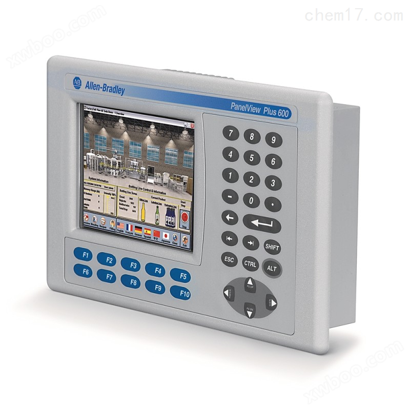
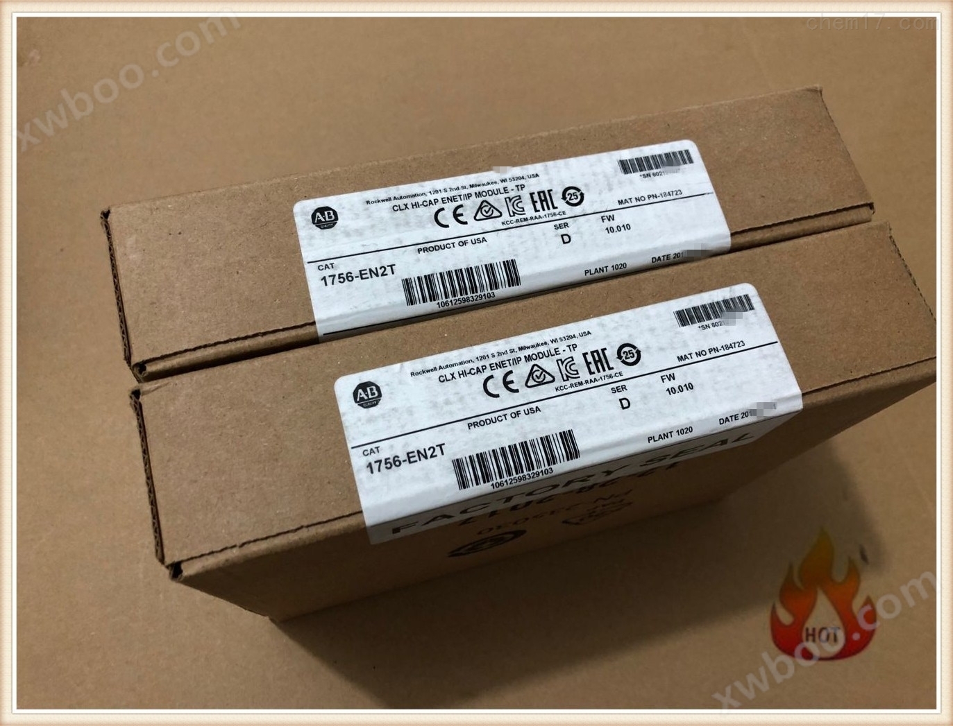
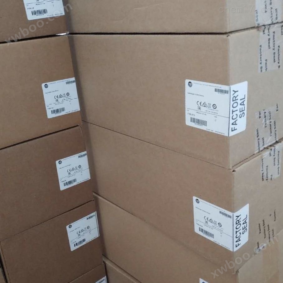
2711P Series AB Rockwell Touchscreen Supply
NegotiableUpdate on 01/22
- Model
- Nature of the Manufacturer
- Producers
- Product Category
- Place of Origin
Overview
PLC, as a general industrial control computer, is an industrial control equipment designed for industrial and mining enterprises. It has an easy interface and a programming language that is easily accepted by engineering and technical personnel. The graphical symbols and expressions of ladder diagram language are quite similar to relay circuit diagrams, and the functions of relay circuits can be easily implemented with only a small number of switch logic control instructions from PLC. This has opened the door for people who are not familiar with electronic circuits, computer principles, and assembly language to use computers for industrial control. 2711P Series AB Rockwell Touchscreen Supply
Product Details
Technical specifications for 2711P-B6C20D9
| manufacturer | Rockwell Automation |
| card | Alan Bradley |
| Part number/catalog number | 2711P-B6C20D9 |
| production line | Panelview 6 Plus |
| Display Size | 5.7-inch |
| display color | color |
| input type | Keyboard/Touch Screen |
| communication | Ethernet and RS-232 |
| input power | 18-30 VDC |
| software | FactoryTalk View Machine Edition |
| memory | 256 MB RAM |
| backlight | non-replaceable |
| communication cable | 2711-NC14 |
| Shipping weight | 6 pounds |
| Shipping dimensions | 14 x 11 x 8 inches |
| series | Series A and Series B |
| firmware | 7.00-8.10 |
Regarding 2711P-B6C20D9
The current Allen Bradley Panelview 6 Plus 2711P-B6C20D9 is an HMI that allows users to interact with their machines. The operator interface has a 5.7-inch color display screen. The Panelview Plus 6 allows users to connect using FactoryTalk View Machine Edition software and Ethernet and RS-232 communication ports with 2711-NC14 communication cables. Users can control the operator interface by inputting information and data through the keyboard/touch screen. This machine is powered by an 18-30 VDC power supply. This machine has the following internal memory: 256 MB RAM. If applicable, the internal backlight replacement part number of this machine cannot be changed. The approximate shipping weight and size are 6 pounds. 14 x 11 x 8 inches. The series seen are A series and B series, and the firmware seen includes 7.00-8. EtherNet/IP (Ethernet Industrial Protocol) is an open industrial network that supports real-time I/O messaging and message exchange. Ethernet ports are connected to controllers on EtherNet/IP networks using network and standard Ethernet connections. This port can also be used for application transfer and printing. Display the EtherNet/IP screen and allow users to modify some EtherNet/IP communication settings of the PanelView terminal. If another Ethernet port is required, the 2711P-RN20 Ethernet communication module can be used for 700 to 1500 terminals. This module has its own IP address. This port has RJ45, 10/100Base-T connectors for network communication and supports MDI/MDI-X connections. The parameters are downloaded together with the application. EtherNet/IP (Ethernet Industrial Protocol) is an open industrial network that supports real-time I/O messaging and message exchange. Ethernet ports are connected to controllers on EtherNet/IP networks using network and standard Ethernet connections. This port can also be used for application transfer and printing. Display the EtherNet/IP screen and allow users to modify some EtherNet/IP communication settings of the PanelView terminal. If another Ethernet port is required, the 2711P-RN20 Ethernet communication module can be used for 700 to 1500 terminals. This module has its own IP address. This port has RJ45, 10/100Base-T connectors for network communication and supports MDI/MDI-X connections. The parameters are downloaded together with the application. EtherNet/IP (Ethernet Industrial Protocol) is an open industrial network that supports real-time I/O messaging and message exchange. Ethernet ports are connected to controllers on EtherNet/IP networks using network and standard Ethernet connections. This port can also be used for application transfer and printing. Display the EtherNet/IP screen and allow users to modify some EtherNet/IP communication settings of the PanelView terminal. If another Ethernet port is required, the 2711P-RN20 Ethernet communication module can be used for 700 to 1500 terminals. This module has its own IP address. This port has RJ45, 10/100Base-T connectors for network communication and supports MDI/MDI-X connections. The parameters are downloaded together with the application. And message exchange. Ethernet ports are connected to controllers on EtherNet/IP networks using network and standard Ethernet connections. This port can also be used for application transfer and printing. Display the EtherNet/IP screen and allow users to modify some EtherNet/IP communication settings of the PanelView terminal. If another Ethernet port is required, the 2711P-RN20 Ethernet communication module can be used for 700 to 1500 terminals. This module has its own IP address. This port has RJ45, 10/100Base-T connectors for network communication and supports MDI/MDI-X connections. The parameters are downloaded together with the application. And message exchange. Ethernet ports are connected to controllers on EtherNet/IP networks using network and standard Ethernet connections. This port can also be used for application transfer and printing. Display the EtherNet/IP screen and allow users to modify some EtherNet/IP communication settings of the PanelView terminal. If another Ethernet port is required, the 2711P-RN20 Ethernet communication module can be used for 700 to 1500 terminals. This module has its own IP address. This port has RJ45, 10/100Base-T connectors for network communication and supports MDI/MDI-X connections. The parameters are downloaded together with the application. This port can also be used for application transfer and printing. Display the EtherNet/IP screen and allow users to modify some EtherNet/IP communication settings of the PanelView terminal. If another Ethernet port is required, the 2711P-RN20 Ethernet communication module can be used for 700 to 1500 terminals. This module has its own IP address. This port has RJ45, 10/100Base-T connectors for network communication and supports MDI/MDI-X connections. The parameters are downloaded together with the application. This port can also be used for application transfer and printing. Display the EtherNet/IP screen and allow users to modify some EtherNet/IP communication settings of the PanelView terminal. If another Ethernet port is required, the 2711P-RN20 Ethernet communication module can be used for 700 to 1500 terminals. This module has its own IP address. This port has RJ45, 10/100Base-T connectors for network communication and supports MDI/MDI-X connections. The parameters are downloaded together with the application. If another Ethernet port is required, the 2711P-RN20 Ethernet communication module can be used for 700 to 1500 terminals. This module has its own IP address. This port has RJ45, 10/100Base-T connectors for network communication and supports MDI/MDI-X connections. The parameters are downloaded together with the application. If another Ethernet port is required, the 2711P-RN20 Ethernet communication module can be used for 700 to 1500 terminals. This module has its own IP address. This port has RJ45, 10/100Base-T connectors for network communication and supports MDI/MDI-X connections. The parameters are downloaded together with the application.
2711P Series AB Rockwell Touchscreen Supply 2711P Series AB Rockwell Touchscreen Supply
RPI determines the rate at which the module broadcasts data. The time range is from 200 microseconds to 750 milliseconds. After one RPI time frame has passed,
If there is no state change (COS) occurring within the RPI time frame when the module starts broadcasting data (also known as periodic data exchange),
The module broadcasts data at the RPI * rate. Due to the asynchronous nature of COS functionality and RPI with logical scanning,
Therefore, it is possible that the input has undergone a state change during program scanning execution. If this is crucial, you can create an input data buffer,
In this way, the user's logic program has a stable data backup during its scanning. You can use the Synchronized Copy (CPS) command to transfer the input from the input label
Copy the data to another structure and then use the data from the structure. The values of RPI and COS are used to determine when a module is widely distributed within its own rack
Broadcast data, but only the RPI value can determine when the host controller receives data from the network. When creating an input module on a remote framework
When the RPI value is reached, in addition to notifying the module to broadcast data within its own rack, RPI also "reserves" a segment (spot) in the control network data flow. 'Reserved'
The timing of the segment may or may not match the RPI value. But the host controller can at least receive data at the RPI rate. If the module
Located on the same rack as the host module controller, when the host controller sends out data, the module receives the data almost simultaneously. All tasks in each task
After the program scan is completed, send the data. If the output module is not on the same framework as the host controller (such as through ControlNet or Ethernet/IP)
The host controller will send data to the output module at the RPI rate based on the connected remote framework. RPI also 'reserves' a segment in controlling network data flow
(spot)。 The timing of the 'reserved' point may or may not match the RPI value. But the output module can at least receive at the RPI rate
data
The RTS value determines when the module scans its channels and broadcasts data (updates the input data buffer and broadcasts data). When does the RPI module broadcast input
The current data in the data buffer is not scanned (updated) in the channel. Every time the module resets the RPI timer, it will generate RTS transmission. If R
If the TS value is less than or equal to the RPI value, the data broadcasted by the module each time is the recently updated channel data. This module only broadcasts at RTS rate. If R
If the TS value is greater than the RPI value, the module can broadcast at either the RTS rate or RPI rate. RTS and RPI values are used to determine when a module broadcasts within its own rack
However, only the RPI value can determine when the host controller receives data from the network. RPI is still "retaining" a segment (s) in the control network data flow
pot)。 The timing of the 'reserved' segment may or may not match the RPI value. But the host controller can at least receive at the RPI rate
data The RPI value determines when the host controller broadcasts output data to the module. If the module and the host module controller are located on the same rack, when the host controller
After the controller sends out the data, the module receives it almost simultaneously. If the output module is not on the same framework as the host controller (e.g. through Contro)
The host controller will send data to the output module at the RPI rate using a remote framework connected via lNet or Ethernet/IP. RPI is also controlling network data
Keep a segment (spot) in the stream. The timing of the 'reserved' point may or may not match the RPI value. But the output module can at least press
*The RPI rate receives data. Each I/O module in the ControlLogix system must belong to a ControlLogix controller. Host control
The device stores configuration data for each I/O module it possesses, and depending on the installation location of the I/O module, the module can be either local or remote.
The host controller sends I/O configuration data to specify the working behavior of the I/O module and initiates the actions of the I/O module within the control system. Each ControlLogix
The I/O module must maintain continuous communication with its host controller in order to function properly.
Typically, each I/O module has only one host because when communication with the host controller stops, the listen only controller will be lost
Lost connection with module. Users can define multiple hosts for an input module. If multiple controllers have the same input module, then each controller
The same configuration of the input module must be maintained. The output module only allows one host.
The interface module is an 8-axis module that serves as a link between the ControlLogix platform and the drive system,
Complete operations on 1 to 8 position axes or speed axes. The communication link between the module and the driver adopts fiber optic media and uses a string that complies with the IEC-61491 standard
Real time communication system protocol. The interface is a recognized digital open standard with synchronous multi axis motion control
Ability to control. This interface is designed specifically for efficient data transmission and is particularly suitable for servo control applications. The interface adopts a circular topology structure
Having one master and multiple followers (axis). The fiber optic ring starts and shuts down simultaneously with the main (). The fiber optic transmitter of the module adopts a wavelength of 650nm,
This wavelength generates visible light from the port. Users can use plastic optical fiber (POF) or Hard Cladd Silica (HCS?) cables. Conveyors and connectors
The connection of the receiver adopts plugs that comply with the F-SMA standard and can be matched with F-SMA screw connectors. 2090-SCEPx-0 (without casing) [1]
2090-SCVPx-0 (standard casing)
2090-SCNPx-0 (nylon sleeve)
Plastic fiber optic cable users can use a 1000 μ m plastic unidirectional fiber optic cable. The transmission range of plastic fiber optic cables is 1-32 meters. Allen-Bradley
Provide fiber optic cables assembled with various sleeves. The optional cable types are: sleeveless (chlorinated polyethylene), suitable for use inside electrical cabinets; Standard casing(
Polyethylene chloride, suitable for use inside electrical cabinets; Nylon sleeve, suitable for harsh environments 2090-SCVGx-0 [2] glass fiber optic cable users can use 200
μ m glass fiber optic cable. The transmission range of glass fiber optic cable is 1-200 meters to 200 meters. Allen Bradley offers assembly using standard tubing (polyvinyl chloride)
The glass fiber optic cable is suitable for ordinary environments.
[1] X determines the length, measured in meters. Choose 1, 3, 5, 8, 10, 15, 20, 25, or 32 meters. [2] X has determined the length in meters. choice
1, 3, 5, 8, 10, 15, 20, 25, 32, 50, 100, 150 or 200 meters.
The servo module is a 2-axis closed-loop servo module that can receive trajectory information from the ControlLogix controller. By monitoring the position feedback of the orthogonal encoder input
And by issuing a simulated command reference to the driver, the servo module can ensure that the actuator (motor) follows the given trajectory. Using position feedback as input, ± 10V
Using analog signals as output, the position and velocity loops can complete closed-loop adjustment every 200 microseconds.
Important note: The servo module must be in the same rack as the ControlLogix controller that controls the servo module. If we want to achieve distributed motion control in different positions
A ControlLogix controller should be installed on each rack with servo modules inserted. 1756 SYNC SynchLink module connects ControlLogix rack
Connect to SynchLink fiber optic communication link. SynchLink provides time synchronization and data broadcasting capabilities for distributed motion and coordinated drive control. The following devices are supported
SynchLink:
1756-SYNC SynchLink Module 1756-DM Driver Module PowerFlex 700S Driver
The 1756-SYNC module performs three functions: coordinating CST time between multiple ControlLogix racks; High speed transfer from one framework to another*
The data; Allow one controller to use motion axis data from another rack controller; The 1756-DM driver module allows users to split the installed Reliance into
Update and upgrade the Power Distribution System (DPS) to a ControlLogix based system. Each driver module interface and a separate power module interface (PMI) box
Frame connection. Users can use 1756-DM to accelerate the modernization process of existing power bridges, achieving a leap from analog control to digital control.
Planning network communication
On the local rack, the ControlLogix controller communicates with the 1756 module through the backplane. The ControlLogix controller can also communicate with the communication interface module through the backplane,
Monitor and control I/O connected to EtherNet/IP, ControlNet, DeviceNet, and Universal Remote I/O networks, and monitor Foundation fieldbus (Found)
Fieldbus data. EtherNet/IP, ControlNet, DeviceNet, DH+, Universal Remote I/O, RS-232 serial port (DF1 protocol), and DH-485
On the network, the ControlLogix controller can transmit or receive general communication information.
Messages can be directly transmitted from one communication interface module to another module through the backplane. Users can transmit information across 4 racks (8 communication relay stations).
Users should determine the communication structure based on network needs. There are three main types of networks:
Information network: providing connections between workshops and manufacturing systems; Can connect to main computers from multiple manufacturers; Capable of transmitting large data files; Support standards
Network management and troubleshooting tools;
Control network: provide real-time performance; Having certainty and repeatability; Support peer-to-peer communication; Can be connected to programmable controllers, personal computers, and human-machine interface devices
Drivers, motion control devices, etc; Support programming and device configuration;
Device network: Reduce wiring costs as devices are no longer directly connected to programmable controllers; Support device level fault diagnosis; Can connect to devices from multiple manufacturers
NetLinx structure
For the three open networks (DeviceNet, ControlNet, and EtherNet/IP) that support ControlLogix devices, the NetLinx architecture is the foundation. NetLinx
The structure combines network services, CIP (Control and Information Protocol), and open software interfaces together. The specially designed NetLinx architecture includes device network, control network, and
Information network. According to specific application requirements, users can mix and match one layer, two layers, or all three layers of the network. Users can seamlessly transfer data between networks without any additional requirements
External programming, configuration, or creation of routing tables. NetLinx is' wire independent '. This means that users can choose components and media based on specific application scenarios.
According to the user's choice, for example, EtherNet/IP based on EtherNet TCP/IP is suitable for information and control, while ControlNet is suitable for deterministic control, DeviceN
ET is suitable for device level, and users can design control solutions using technologies that integrate new and advanced features. In order to further develop users' systems, the NetLinx architecture
Many open technologies, such as OLE technology (OPC) for process control and RSLinx and IOLinx from Rockwell software, are mixed to achieve user satisfaction
The seamless connection between computer systems and commercial hardware and software. EtherNet Industrial Protocol (EtherNet/IP) is an open industrial network standard that supports implicit messaging
Real time I/O messages, explicit messages (message exchange), or both, and commonly used commercial Ethernet communication chips and physical media are used.
The EtherNet/IP standard adopts the IEEE 802.3 Physical Media and Data Link standard; EtherNet TCP/IP protocol suite (Transmission Control Protocol/Internet Protocol),
Ethernet industry standards; Control and Information Protocol (CIP), which provides real-time I/O messages and information/peer-to-peer communication;
The ControlLogix system establishes a communication link between two devices. The connection can be: from the controller to the local I/O module or local communication module; Controller to
Remote I/O module or remote communication module; Communication between producer and customer tags
By configuring the communication between the controller and other devices in the system, users can indirectly determine the number of connections used by the controller. The ControlLogix system supports both reserved and non reserved connections.
A device that can recognize one device through a predetermined connection allows users to repeatedly send and receive data at a predetermined rate, known as Request Packet Interval (RPI). For example, to
The connection of an I/O module is a predetermined connection because the user repeatedly receives data from the module. Other scheduled connections include connections to the following devices: communication devices; Production
User and customer labels; For ControlNet, users must use RSNetWorx to activate all scheduled connections and establish a Network Update Time (NUT) for the network.
An unplanned connection refers to the message transmission between controllers triggered by a program (such as MSG instruction). When needed, non scheduled messages allow users to send and receive data.
Large quantity of producer and customer labels
Controller support: As: Controller support: Producer (number of producer labels) ≤ 127 Customer (number of customer labels) ≤ 250
The total number of producer and customer tags supported by a controller (which is also the number of large connections) is: production type number+consumption type tag number ≤ 250
As the number of customer tags increases, the number of available producer tags decreases.
Important note: The total number of producer or customer tags is limited by the number of connections. If the controller uses all its connections for I/O and communication devices, there are no connections left for producers and customers
label
Unplanned connections are used to transmit data to other devices, such as other controllers or operator devices. Some messages require an unplanned connection to send or receive data. when
After the message is sent, some messages also have options to keep the connection open (buffered) or close the connection. The following table shows which messages occupy a connection: If a message is repeatedly executed,
Buffer the connection. This can keep the connection open and optimize execution time. Opening a connection every time will increase the execution time of the message. If a message is only occasionally delivered
If it runs once, do not buffer the connection. Once communication is completed, the connection will be closed and released to other applications.
No matter how many devices are on the message path, each connection occupies one connection. To save connections, users can configure a communication to read from or write to multiple devices.
Similar Product Recommend